ML2, Open vSwitch, OpenStack, Overlays

OVS ARP Responder – Theory and Practice

Prefix

In the GRE tunnels post I’ve explained how overlay networks are used for connectivity and tenant isolation. In the l2pop post, or layer 2 population, I explained how OVS forwarding tables are pre-populated when instances are brought up. Today I’ll talk about another form of table pre-population – The ARP table. This feature has been introduced with this patch by Edouard Thuleau, merged during the Juno development cycle.

ARP – Why do we need it?

In any environment, be it the physical data-center, your home, or a virtualization cloud, machines need to know the MAC, or physical network address, of the next hop. For example, let there be two machines connected directly via a switch:

The first machine has an IP address of 10.0.0.1, and a MAC address of 0000:DEAD:BEEF,

while the second machine has an IP address of 10.0.0.2, and a MAC address of 2222:FACE:B00C.

I merrily log into the first machine and hit ‘ping 10.0.0.2’, my computer places 10.0.0.2 in the destination IP field of the IP packet, then attempts to place a destination MAC address in the Ethernet header, and politely bonks itself on its digital forehead. Messages must be forwarded out of a computer’s NIC with the destination MAC address of the next hop (In this case 10.0.0,2, as they’re directly connected). This is so switches know where to forward the frame to, for example.

Well, at this point, the first computer has never talked to the second one, so of course it doesn’t know its MAC address. How do you discover something that you don’t know? You ask! In this case, you shout. 10.0.0.1 will flood, or broadcast, an ARP request saying: What is the MAC address of 10.0.0.2? This message will be received by the entire broadcast domain. 10.0.0.2 will receive this message (Amongst others) and happily reply, in unicast: I am 10.0.0.2 and my MAC address is 2222:FACE:B00C. The first computer will receive the ARP reply and will then be able to fill in the destination MAC address field, and finally send the ping.

Will this entire process be repeated every time the two computers wish to talk to each other? No. Sane devices keep a local cache of ARP responses. In Linux you may view the current cache with the ‘arp’ command.

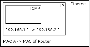
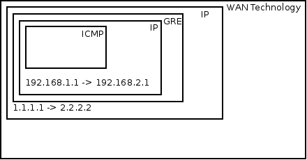
A slightly more complex case would be two computers separated by a layer 3 hop, or a router. In this case the two computers are in different subnets, for example 10.0.0.0/8 and 20.0.0.0/8. When the first computer pings the second one, the OS will notice that the destination is in a different subnet, and thus forward the message to the default gateway. In this case the ARP request will be sent for the MAC address of the pre-configured default gateway IP address. A device only cares about the MAC address of the next hop, not of the final destination.

The absurdity of L2pop without an ARP responder

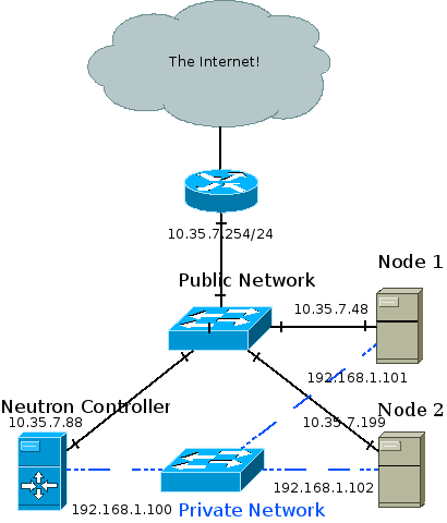
Let there be VM 1 hosted on compute node A, and VM 2 hosted on compute node B.

With l2pop disabled, when VM 1 sends an initial message to VM 2, compute node A won’t know the MAC address of VM 2 and will be forced to flood the message out all tunnels, to all compute nodes. When the reply is received, node A would learn the MAC address of VM 2 along with the remote node and tunnel ID. This way, future floods are prevented. L2pop prevents even the initial flood by pre-populating the tables, as the Neutron service is aware of VM MAC addresses, scheduling, and tunnel IDs. More information may be found in the dedicated L2pop post.

So, we optimized one broadcast, but what about ARPs? Compute node A is aware of the MAC address (And whereabouts) of VM 2, but VM 1 isn’t. Thus, when sending an initial message from VM 1 to 2, an ARP request will be sent out. Compute node A knows the MAC address of VM 2 but chooses to put a blindfold over its eyes and send a broadcast anyway. Well, with the ARP responder feature this is no longer case.

The OVS ARP responder – How does it work?

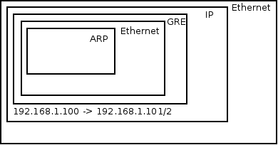
A new table is inserted into the br-tun OVS bridge, to be used as an ARP table. Whenever a message is received by br-tun from a local VM, it is classified into unicast, broadcast/multicast and now ARP requests. ARP requests go into the ARP table, where pre-learned MAC addresses (Via l2pop, more in a minute) reside. Rows in this table are then matched against the (ARP protocol, network, IP of the requested VM) tuple. The resulting action is to construct an ARP reply that will contain the IP and MAC addresses of the remote VM, and will be sent back from the port it came in on to the VM making the original request. If a match is not found (For example, if the VM is trying to access a physical device not managed by Neutron, thus was never learned via L2pop), the ARP table contains a final default flow, to resubmit the message to the broadcast/multicast table, and the message will be treated like any old broadcast.

The table is filled whenever new L2pop address changes come in. For example, when VM 3 is hosted on compute C, both compute nodes A and B get a message that a VM 3 with IP address ‘x’ and MAC address ‘y’ is now on host C, in network ‘z’. Thus, compute nodes A and B can now fill their respective ARP tables with VM 3’s IP and MAC addresses.

The interesting code is currently at:

https://github.com/openstack/neutron/blob/master/neutron/plugins/openvswitch/agent/ovs_neutron_agent.py#L484

For help on reading OVS tables, and an explanation of OVS flows and how they’re comprised of match and action parts, please see a previous post.

Blow by blow:

Here’s the action part:

            actions = (‘move:NXM_OF_ETH_SRC[]->NXM_OF_ETH_DST[],’ – Place the source MAC address of the request (The requesting VM) as the new reply’s destination MAC address

                       ‘mod_dl_src:%(mac)s,’ – Put the requested MAC address of the remote VM as this message’s source MAC address

                       ‘load:0x2->NXM_OF_ARP_OP[],’ – Put an 0x2 code as the type of the ARP message. 0x2 is an ARP response.

                       ‘move:NXM_NX_ARP_SHA[]->NXM_NX_ARP_THA[],’ – Place the ARP request’s source hardware address (MAC) as this new message’s ARP target / destination hardware address

                       ‘move:NXM_OF_ARP_SPA[]->NXM_OF_ARP_TPA[],’ – Place the ARP request’s source protocol / IP address as the new message’s ARP destination IP address

                       ‘load:%(mac)#x->NXM_NX_ARP_SHA[],’ – Place the requested VM’s MAC address as the source MAC address of the ARP reply

                       ‘load:%(ip)#x->NXM_OF_ARP_SPA[],’ – Place the requested VM’s IP address as the source IP address of the ARP reply

                       ‘in_port’ % {‘mac’: mac, ‘ip’: ip}) – Forward the message back to the port it came in on

Here’s the match part:

            self.tun_br.add_flow(table=constants.ARP_RESPONDER, – Add this new flow to the ARP_RESPONDER table

                                 priority=1, – With a priority of 1 (Another, default flow with the lower priority of 0 is added elsewhere in the code)

                                 proto=‘arp’, – Match only on ARP messages

                                 dl_vlan=lvid, – Match only if the destination VLAN (The message has been locally VLAN tagged by now) matches the VLAN ID / network of the remote VM

                                 nw_dst=%s % ip, – Match on the IP address of the remote VM in question

                                 actions=actions)

Example:

An ARP request comes in.

In the Ethernet frame, the source MAC address is A, the destination MAC address is FFFF:FFFF:FFFF.

In the ARP header, the source IP address is 10.0.0.1, the destination IP is 10.0.0.2, the source MAC is A, and the destination MAC is FFFF:FFFF:FFFF.

Please make sure that entire part makes sense before moving on.

Assuming L2pop has already learned about VM B, the hypervisor’s ARP table will already contain an ARP entry for VM B, with IP 10.0.0.2 and MAC B.

Will this message be matched? Sure, the proto is ‘arp’, they’re in the same network so dl_vlan will be correct, and nw_dst (This part is slightly confusing) will correctly match on the destination IP address of the ARP header, seeing as ARP replaces IP in the third layer during ARP messages.

What will be the action? Well, we’d expect an ARP reply. Remember that ARP replies reverse the source and destination so that the source MAC and IP inside the ARP header are the MAC and IP addresses of the machine we asked about originally, and the destination MAC address in the ARP header is the MAC address of the machine originating the ARP request. Similarly we’d expect that the source MAC of the Ethernet frame would be the MAC of the VM we’re querying about, and the destination MAC of the Ethernet frame would be the MAC of the VM originating the ARP request. If you carefully observe the explanation of the action part above, you would see that this is indeed the case.

Thus, the source MAC of the Ethernet frame would be B, the destination MAC A. In the ARP header, the source IP 10.0.0.2 and source MAC B, while the destination IP 10.0.0.1 and destination MAC A. This ARP reply will be forwarded back through the port which it came in on and will be received by VM A. VM A will unpack the ARP reply and find the MAC address which it queried about in the source MAC address of the ARP header.

Turning it on

Assuming ML2 + OVS >= 2.1:

  • Turn on GRE or VXLAN tenant networks as you normally would
  • Enable l2pop
    • On the Neutron API node, in the conf file you pass to the Neutron service (plugin.ini / ml2_conf.ini):
[ml2]
mechanism_drivers = openvswitch,l2population
    • On each compute node, in the conf file you pass to the OVS agent (plugin.ini / ml2_conf.ini):
[agent]
l2_population = True
  • Enable the ARP responder: On each compute node, in the conf file you pass to the OVS agent (plugin.ini / ml2_conf.ini):
[agent]
arp_responder = True

To summarize, you must use VXLAN or GRE tenant networks, you must enable l2pop, and finally you need to enable the arp_responder flag in the [agent] section in the conf file you pass to the OVS agent on each compute node.

Thanks

Props to Edouard Thuleau for taking the initiative and doing the hard work, and for the rest of the Neutron team in the lengthy review process! It took us nearly 8 months but we finally got it merged, in fantastic shape.

Standard
ML2, OpenStack, Overlays

ML2 – Address Population

Why do we need it, whatever it is?

VM unicast, multicast and broadcast traffic flow is detailed in my previous post:

Tunnels in Openstack Neutron

TL;DR: Agent OVS flow tables implement learning. That is, any unknown unicast destination (IE: MAC addresses the virtual switch is not familiar with), multicast or broadcast traffic is flooded out tunnels to all other compute nodes. Any incoming traffic is used for its source MAC address. That MAC address is added to a learning table, so future traffic to that MAC address is not flooded but sent directly to the hosting node. There’s several inefficiencies here:

  1. The MAC addresses aren’t initially known by the agents, but the Neutron service has full knowledge of the topology
  2. There’s still a lot of broadcasts going around in the form of ARP requests. Maybe we can optimize those away?
  3. More about broadcasts: What if a node isn’t hosting any ports in a specific network? Should this node receive broadcast traffic designated to that network?

A great visual explanation for the third point, stolen shamelessly from the official OpenStack documentation:

Overview

When using the ML2 plugin with tunnels and a new port goes up, ML2 sends a update_port_postcommit notification which is picked up and processed by the l2pop mechanism driver. l2 pop then gathers the IP and MAC of the port, as well as the host that the port was scheduled on; It then sends an RPC notification to all layer 2 agents. The agents uses the notification to solve the three issues detailed above.

Configuration

ml2_conf.ini:
[ml2]
mechanism_drivers = ..., l2population, ...
[agent]
l2_population = True

Deep-Dive & Code

plugins/ml2/drivers/l2pop/mech_driver.py:update_port_postcommit calls _update_port_up. In _update_port_up we send the new ports’ IP and MAC address to all agents via a ‘add_fdb_entries’ RPC fanout cast. Additionally, if this new port is the first port in a network on the scheduled agent, then we send all IP and MAC addresses on the network to that agent.

‘add_fdb_entries’ is picked up via agent/l2population_rpc.py:add_fdb_entries, which calls fdb_add if the RPC call was a fanout, or directed to the local host.

fdb_add is implemented by the OVS and LB agents: plugins/openvswitch/agent/ovs_neutron_agent.py and plugins/linuxbridge/agent/linuxbridge_neutron_agent.py.

In the OVS agent, fdb_add accomplishes three main things:

For each port received:

  1. Setup a tunnel to the remote agent if one does not already exist
  2. If its a flood entry, setup a flood flow to the remote network. Reminder: A flood flow is sent out to all agents in case a port goes up which happens to be the first port for an agent & network pair
  3. If its a unicast entry, add it to the unicast learning table
  4. A big fat TO-DO about ARP replies. Implemented in the Icehouse release with this patch: https://review.openstack.org/#/c/49227/

Finally, with l2_population = True, a bunch of code is in the ovs agent is disabled. tunnel_update and tunnel_sync RPC messages are ignored, and replaced by fdb_add, fdb_remove.

Supported Topologies

All of this is fully supported since the Havana release when using GRE and VXLAN tunneling with the ML2 plugin, apart from the ARP resolution optimization which is implemented only for the Linux bridge agent with the VXLAN driver. ARP resolution will be added to the OVS agent with GRE and VXLAN drivers in the Icehouse release.

Links

http://docs.openstack.org/admin-guide-cloud/content/ch_networking.html#ml2_l2pop_scenarios

Standard
Open vSwitch, OpenStack, Overlays

GRE Tunnels in OpenStack Neutron

In the last post we gave context – How are GRE tunnels used outside of the virtualization world.

In this post we’ll examine how GRE tunnels are an alternative to VLANs as an OpenStack Neutron cloud networking configuration. GRE tunnels like VLANs have two main roles:

  1. To provide connectivity between all VMs in a tenant network, regardless of which compute node the VMs reside in
  2. To segregate VMs in different tenant networks

Example Topology

Topology Neutron GRE

The recommended deployment topology is more complicated and can involve an API, management, data and external network. In my test setup the Neutron controller is also a compute node, and all three nodes are connected to a private network through which the GRE tunnels are created and VM traffic is forwarded. Management traffic also goes through the private network. The public network is eventually connected to the internet and is also how I SSH into the different machines from my development station.

I achieved the topology using oVirt to provision three VMs across two physical hosts. The two hosts are physically connected to a public network and to each other. The three VMs are ran on a RHEL 6.5 beta release with kernel that supports ip namespaces (For example: 2.6.32-130). I used Packstack to install OpenStack Havana which installed the correct version of Open vSwitch (1.11) that supports GRE tunneling.

High Level View

Whenever a layer 2 agent (Open vSwitch) goes up it uses OpenStack’s messaging queue to notify the Neutron controller that it’s up. A GRE tunnel is then formed between the node and the controller, and the controller notifies the other nodes that a new node has joined the party. A GRE tunnel is then formed between the new node and every pre-existing node. In other words, a full mesh is formed between the controller and all compute nodes, and the tunnel ID header field in the GRE header is used to differentiate between different tenant networks. The GRE tunnels encapsulate Ethernet frames leaving the VMs and thus create a giant broadcast domain per tenant network, spanning over all compute nodes.

Medium Level View

VM Connectivity

VMs are connected as usual via tap devices to an Open vSwitch bridge called br-int. This is actually a simplification which will be expanded upon later in this post. br-int is connected via an internal OVS patch port to another bridge called br-tun. This internal patch port is similar to a veth pair: A Linux networking device pair where if a packet is sent down one end it will magically appear at the other end. Such a device is created via:

[root@NextGen1 ~]# ip link add veth0 type veth peer name veth1

The ovs internal patch port however is not registered as a normal networking device. It is not visible with “ip address” or “ifconfig”. The important bit is that both br-int and br-tun view it as a normal switch port.

If you are unfamiliar with Open vSwitch flow tables you might want to consider stopping by a previous post: Open vSwitch Basics.

br-int, in a GRE configuration, works as a normal layer 2 learning switch. We can confirm this by looking at its flow table:

[root@NextGen1 ~]# ovs-ofctl dump-flows br-int
NXST_FLOW reply (xid=0x4):
cookie=0x0, duration=176865.121s, table=0, n_packets=64757, n_bytes=13893740, idle_age=13, hard_age=65534, priority=1 actions=NORMAL

We can see that br-int is in “normal” mode.

The interesting part is then: What’s going on with br-tun?

[root@NextGen1 ~]# ovs-vsctl show
911ff1ca-590a-4efd-a066-568fbac8c6fb
[... Bridge br-int omitted ...]
    Bridge br-tun
        Port patch-int
            Interface patch-int
                type: patch
                options: {peer=patch-tun}
        Port br-tun
            Interface br-tun
                type: internal
        Port "gre-2"
            Interface "gre-2"
                type: gre
                options: {in_key=flow, local_ip="192.168.1.100", out_key=flow, remote_ip="192.168.1.101"}
        Port "gre-1"
            Interface "gre-1"
                type: gre
                options: {in_key=flow, local_ip="192.168.1.100", out_key=flow, remote_ip="192.168.1.102"}

We can see that an interface called “patch-int” connects br-tun to br-int. More important are the two GRE interfaces – Both with a tunnel source IP of 192.168.1.100 (The controller machine in the topology above), but with different tunnel remote IPs: 101 and 102.

When the two local VMs want to communicate with one another br-tun is out of the picture. The messages reach br-int, which acts as a normal layer 2 learning switch and acts accordingly. But, when a VM wants to communicate with a VM on another compute node, or when it needs to send a broadcast or multicast message then things get interesting and br-tun comes into play.

In our example, let’s assume a tenant network 10.0.0.0/8 exists. 10.0.0.1 will be a VM on the Neutron controller (Remember in my test lab it’s also a compute node) and VM 10.0.0.2 will reside on “Node 1”. When 10.0.0.1 pings 10.0.0.2 the following flow occurs:

VM1 pings VM2. Before VM1 can create an ICMP echo request message, VM1 must send out an ARP request for VM2’s MAC address. A quick reminder about ARP encapsulation – It is encapsulated directly in an Ethernet frame – No IP involved (There exists a base assumption that states that ARP requests never leave a broadcast domain therefor IP packets are not needed). The Ethernet frame leaves VM1’s tap device into the host’s br-int. br-int, acting as a normal switch, sees that the destination MAC address in the Ethernet frame is FF:FF:FF:FF:FF:FF – The broadcast address. Because of that it floods it out all ports, including the patch cable linked to br-tun. br-tun receives the frame from the patch cable port and sees that the destination MAC address is the broadcast address. Because of that it will send the message out all GRE tunnels (Essentially flooding the message). But before that, it will encapsulate the message in a GRE header and an IP packet. In fact, two new packets are created: One from 192.168.1.100 to 192.168.1.101, and the other from 192.168.1.100 to 192.168.1.102. The encapsulation over the GRE tunnels looks like this:

GRE Encapsulation ARP

GRE normally encapsulates IP but can also wrap Ethernet

Each tenant network is mapped to a GRE tunnel ID which is written in the GRE header. Both compute nodes get the message. Node 1 in particular receives the message, sees that it is destined to his own IP address. The outer IP header has “GRE” as the “Next Protocol” field. In the GRE header the tunnel ID is written and because it is correctly configured and matches Node 1’s local configuration the message is not dropped, but the IP and GRE headers are discarded. The Ethernet frame is forwarded to br-int which floods it to all VMs. VM 2 receives the message and responds to the ARP request with his own MAC address. The reverse process then occurs and VM1 gets his answer, at which point it can initiate an ICMP echo request directly to VM 2.

For unicast traffic we really want to avoid flooding the message out to all GRE tunnels. Ideally we’d want to forward the message only to the host where the VM resides in. This is accomplished by learning MAC addresses on incoming traffic from GRE tunnels in to br-int. Infact, earlier when the ARP reply came back from the GRE tunnel into the compute node VM 1 resides in, a new flow was inserted into br-tun’s flow table. The new flow matches against the tenant’s network tunnel ID, with a destination MAC address of VM2, and the flow’s action is to forward it to the GRE tunnel that reaches VM 2’s compute node.

To summarize, we can conclude that the flow logic on br-tun implements a learning switch but with a GRE twist. If the message is to a multicast, broadcast, or unknown unicast address it is forwarded out all GRE tunnels. Otherwise if it learned the destination MAC address via earlier messages (By observing the source MAC address, tunnel ID and incoming GRE port) then it forwards it to the correct GRE tunnel.

Low Level View

[root@NextGen1 ~]# ovs-ofctl dump-flows br-tun
NXST_FLOW reply (xid=0x4):
 cookie=0x0, duration=182369.287s, table=0, n_packets=5996, n_bytes=1481720, idle_age=52, hard_age=65534, priority=1,in_port=3 actions=resubmit(,2)
 cookie=0x0, duration=182374.574s, table=0, n_packets=14172, n_bytes=3908726, idle_age=5, hard_age=65534, priority=1,in_port=1 actions=resubmit(,1)
 cookie=0x0, duration=182370.094s, table=0, n_packets=0, n_bytes=0, idle_age=65534, hard_age=65534, priority=1,in_port=2 actions=resubmit(,2)
 cookie=0x0, duration=182374.078s, table=0, n_packets=3, n_bytes=230, idle_age=65534, hard_age=65534, priority=0 actions=drop
 cookie=0x0, duration=182373.435s, table=1, n_packets=3917, n_bytes=797884, idle_age=52, hard_age=65534, priority=0,dl_dst=00:00:00:00:00:00/01:00:00:00:00:00 actions=resubmit(,20)
 cookie=0x0, duration=182372.888s, table=1, n_packets=10255, n_bytes=3110842, idle_age=5, hard_age=65534, priority=0,dl_dst=01:00:00:00:00:00/01:00:00:00:00:00 actions=resubmit(,21)
 cookie=0x0, duration=182103.664s, table=2, n_packets=5982, n_bytes=1479916, idle_age=52, hard_age=65534, priority=1,tun_id=0x1388 actions=mod_vlan_vid:1,resubmit(,10)
 cookie=0x0, duration=182372.476s, table=2, n_packets=14, n_bytes=1804, idle_age=65534, hard_age=65534, priority=0 actions=drop
 cookie=0x0, duration=182372.099s, table=3, n_packets=0, n_bytes=0, idle_age=65534, hard_age=65534, priority=0 actions=drop
 cookie=0x0, duration=182371.777s, table=10, n_packets=5982, n_bytes=1479916, idle_age=52, hard_age=65534, priority=1 actions=learn(table=20,hard_timeout=300,priority=1,NXM_OF_VLAN_TCI[0..11],NXM_OF_ETH_DST[]=NXM_OF_ETH_SRC[],load:0->NXM_OF_VLAN_TCI[],load:NXM_NX_TUN_ID[]->NXM_NX_TUN_ID[],output:NXM_OF_IN_PORT[]),output:1
 cookie=0x0, duration=116255.067s, table=20, n_packets=3917, n_bytes=797884, hard_timeout=300, idle_age=52, hard_age=52, priority=1,vlan_tci=0x0001/0x0fff,dl_dst=fa:16:3e:1f:19:55 actions=load:0->NXM_OF_VLAN_TCI[],load:0x1388->NXM_NX_TUN_ID[],output:3
 cookie=0x0, duration=182371.623s, table=20, n_packets=0, n_bytes=0, idle_age=65534, hard_age=65534, priority=0 actions=resubmit(,21)
 cookie=0x0, duration=182103.777s, table=21, n_packets=10235, n_bytes=3109310, idle_age=5, hard_age=65534, priority=1,dl_vlan=1 actions=strip_vlan,set_tunnel:0x1388,output:3,output:2
 cookie=0x0, duration=182371.507s, table=21, n_packets=20, n_bytes=1532, idle_age=65534, hard_age=65534, priority=0 actions=drop

Flow Table Flow Chart

Outgoing Traffic

Table 0 has 4 flows. The last one is a default drop flow. br-tun has two GRE tunnels, one to NextGen2 and one to NextGen3, connected to ports 2 and 3. We can see that if the message came from a GRE tunnel it is resubmitted to table 2. br-int is connected via an internal patch port to port 1. Any message coming in from a VM will come in from br-int and will be resubitted to table 1.

Table 1 gets any message that originated from VMs via br-int. If the destination MAC address if a unicast address, it is resubmitted to table 20, otherwise it is resubmitted to table 21. The unicast OR (multicast | broadcast) check is done by observing the 8th bit of the MAC address. All multicast addresses, as well as the broadcast address (FF:FF:FF:FF:FF:FF) have 1 in that slot. Another way to put it – If the 8th bit (Going left to right) is on, then it is NOT a unicast address.

Table 20 gets any unicast VM traffic. This table is populated via learning by observing traffic coming in from the GRE tunnels – We’ll go over this in a bit. If the destination MAC address is known it is forwarded to the appropriate GRE tunnel, otherwise the message is resubmitted to table 21.

Table 21 gets multicast and broadcast traffic as well as traffic destined to unknown MAC addresses. You’ll notice that the first flow in table 21 matches against vlan 1. The vlan is stripped, GRE tunnel ID 0x1388 (5000 in decimal) is loaded and the message is sent out all GRE tunnels. The br-tun flow table doesn’t actually tag any frames, and br-int’s flow table is empty / in normal mode, so where are these tagged frames coming from? If you run ovs-vsctl show, you’ll see that br-int’s ports are VLAN access ports. Every tenant network is provisioned a locally-significant VLAN tag. The ports are vlan tagged by flow tables, but by simply adding the port as a VLAN access port (ovs-vsctl add-port br-int tap0 tag=1). Any traffic coming in from tap0 will be tagged by vlan 1, and any traffic going to tap0 will be stripped of the vlan tag.

Incoming Traffic

Observing table 0 we can see that traffic coming in from GRE tunnels is resubmitted to table 2.

In Table 2 we can see that tunnel ID 0x1388 traffic is resubmitted to table 10 right after being tagged with vlan 1.

Table 10 is where the interesting bit happens. It has a single flow that matches any message. It has a “learn” action that creates a new flow and places it in table 20 – Unicast traffic coming in from VMs.The new flow’s destination MAC address match is the current frame’s source MAC address, and the out port is the current frame’s in port. Finally, the message itself is forwarded to br-int.

Segregation

So far we talked about how GRE tunnels implement VM connectivity. Like VLANs, GRE tunnels need to provide segregation between tenant networks both within a compute node and across compute nodes.

Within a compute node we’ll recall that br-int adds VM taps as VLAN access ports. This means that VMs that are connected to the same tenant network get the same VLAN tag.

Across compute nodes we use the GRE tunnel ID. As discussed previously, each tenant network is provisioned both a GRE tunnel ID and a locally significant VLAN tag. That means that incoming traffic with a GRE tunnel ID is converted to the correct local VLAN tag as can be seen in table 2. The message is then forwarded to br-int already VLAN tagged and the appropriate check can be made.

Standard
Overlays

GRE Tunnels

GRE tunnels are traditionally used for unencrypted IP in IP tunneling.

Usages

If your company has two sites: One in Tel-Aviv Israel and the other in Brno Czech Republic, you might want to connect them in such a way that users feel as if they’re sitting in the same space. The two sites are behind a NAT and so normally a user in one office would not be able to ping or SSH into another user’s machine that’s sitting in the other office. Another usage of tunnels is remote work – A VPN is simply an encrypted tunnel. The idea is to get an IP address from your office’s pool so that employee services “think” you’re actually sitting inside the site walls and not in your pajamas. Another usage would be to enable IPv6 sites to communicate through an IPv4 network.

Example

GRE

The goal is to enable hosts in the Tel-Aviv branch the ability to ping hosts in the Brno branch. Without a tunnel this would not be possible. It’s done via statically configuring a GRE tunnel on both site routers, and requires no involvement from the different ISPs. If encryption is desired it can be later configured on top of the GRE tunnel. Two things need to be done on each router:

  1. Bringing up a (virtual) tunnel device
  2. Defining static routing to the remote 192.168.x.0/24 network through the local tunnel

Great – We configured the routers, but why do the pings suddenly work?

The flow work like this: Host 192.168.1.1 in the TLV office pings 192.168.2.1 in the Brno office. 192.168.1.1 prepares the ping, and the host’s TCP/IP stack implementation compares the source and destination IP addresses and subnet masks and notices (Computers tend to be pedantic like that) that they are in different layer 3 subnets. The host then forwards the packet to 192.168.2.1, but the layer 2 frame to the host’s default gateway MAC address.

The router receives the frame. It sees that the destination MAC address is of its LAN interface, but the destination IP address is not. It then searches for a match to 192.168.2.1 in its routing table, since we configured the router it should have a match for 192.168.2.0/24. The routing entry tells the router to forward the packet through the tunnel interface. Since the tunnel device is configured as a GRE tunnel the router performs the needed encapsulation to make it work.

GRE encapsulation

At this point the encapsulation is as follows:

GRE Encapsulation Before

The router then creates a new IP packet. The source IP will be 1.1.1.1 and the destination IP 2.2.2.2. In the IP packet it marks the next protocol as GRE (Normally it is TCP, UDP or ICMP, for example). It then creates a new GRE header, setting the important “next protocol” field as IPv4. Of course the router discards the Ethernet frame and creates a new layer 2 frame of the WAN technology type the router uses (For example: Cable or xDSL). The final encapsulation looks like this:

GRE Encapsulation After

The effect is that routers throughout the internet see only the packet with a 1.1.1.1 source and 2.2.2.2 destination, routing it normally towards the Brno router. On the other end, the Brno router receives the message and sees that it is destined to itself. The packet says the next protocol in line is GRE, so the router opens the packet’s data as a GRE header. The next protocol field in that header is IPv4, so it opens the next header as an IP packet, and forwards that packet to the 192.168.2.1 host.

Resources

GRE header (Note 16 bit ‘Protocol Type’ and 32 bit optional key used in Neutron and Open vSwitch) – http://en.wikipedia.org/wiki/Generic_Routing_Encapsulation#Packet_header

GRE configuration in Cisco router (May aid understanding even if no interest in the configuration syntax or Cisco gear) – https://supportforums.cisco.com/docs/DOC-2569

Standard