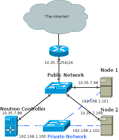
Where Am I?
* Overview and East/West Traffic
SNAT
Floating IPs
Legacy Routing

Overview
DVR aims to isolate the failure domain of the traditional network node and to optimize network traffic by eliminating the centralized L3 agent shown above. It does that by moving most of the routing previously performed on the network node to the compute nodes.
- East/west traffic (Traffic between different networks in the same tenant, for example between different tiers of your app) previously all went through one of your network nodes whereas with DVR it will bypass the network node, going directly between the compute nodes hosting the VMs.
- North/south traffic with floating IPs (Traffic originating from the external network to VMs using floating IPs, or the other way around) will not go through the network node, but will be routed directly by the compute node hosting the VM. As you can understand, DVR asserts that your compute nodes are directly connected to your external network(s).
- North/south traffic for VMs without floating IPs will still be routed through the network node (Distributing SNAT poses another set of challenges).
Each of these traffic categories introduces its own set of complexities and will be explained in separate blog posts. The following sections depicts the requirements and the previous blog post lists the required configuration changes.
Required Knowledge
- Specific sections require OVS flows and tunneling knowledge, which you can obtain from previous posts in my blog (Go from the bottom to the top)
- How ‘legacy’ (Non-distributed, non-HA) routers work
Deployment Requirements
- ML2 plugin
- L2pop mechanism driver enabled
- openvswitch mechanism driver enabled, and the OVS agent installed on all of your compute nodes
- External network connectivity to each of your individual compute nodes
- Juno required tunneling (VXLAN or GRE) tenant networks
- Kilo introduces support for VLAN tenant networks as well
East/West Routing
Logical topology:
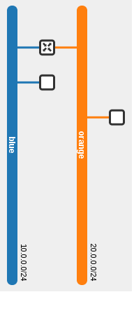
Physical topology:

In this example, the blue VM pings the orange VM. As you can see via the dotted line, routing occurs in the source host. The router present on both compute nodes is the same router.
neutron router-list
+--------------------------------------+-------------+-----------------------+-------------+-------+
| id                                   | name        | external_gateway_info | distributed | ha    |
+--------------------------------------+-------------+-----------------------+-------------+-------+
| 44015de0-f772-4af9-a47f-5a057b28fd72 | distributed | null                  | True        | False |
+--------------------------------------+-------------+-----------------------+-------------+-------+
As we can see, the same router is present on two different compute nodes:
[stack@vpn-6-21 devstack (master=)]$ neutron l3-agent-list-hosting-router distributed
+--------------------------------------+-------------------------+----------------+-------+----------+
| id                                   | host                    | admin_state_up | alive | ha_state |
+--------------------------------------+-------------------------+----------------+-------+----------+
| 6aaeb8a4-b393-4d08-96d2-e66be23216c1 | vpn-6-23.tlv.redhat.com | True           | :-)   |          |
| e8b033c5-b515-4a95-a5ca-dbc919b739ef | vpn-6-21.tlv.redhat.com | True           | :-)   |          |
+--------------------------------------+-------------------------+----------------+-------+----------+
The router namespace was created on both nodes, and it has the exact same interfaces, MAC and IP addresses:
[stack@vpn-6-21 devstack (master=)]$ ip netns
qrouter-44015de0-f772-4af9-a47f-5a057b28fd72

[stack@vpn-6-21 devstack (master=)]$ sudo ip netns exec qrouter-44015de0-f772-4af9-a47f-5a057b28fd72 ip address
1: lo: <LOOPBACK,UP,LOWER_UP> mtu 65536 qdisc noqueue state UNKNOWN group default
    ...
70: qr-c7fa2d36-3d: <BROADCAST,MULTICAST,UP,LOWER_UP> mtu 1500 qdisc noqueue state UNKNOWN group default
    link/ether fa:16:3e:3c:74:9c brd ff:ff:ff:ff:ff:ff
    inet 10.0.0.1/24 brd 10.0.0.255 scope global qr-c7fa2d36-3d
    ...
71: qr-a3bc956c-25: <BROADCAST,MULTICAST,UP,LOWER_UP> mtu 1500 qdisc noqueue state UNKNOWN group default
    link/ether fa:16:3e:a3:3b:39 brd ff:ff:ff:ff:ff:ff
    inet 20.0.0.1/24 brd 20.0.0.255 scope global qr-a3bc956c-25
    ...
[stack@vpn-6-23 devstack (master=)]$ ip netns
qrouter-44015de0-f772-4af9-a47f-5a057b28fd72

[stack@vpn-6-23 devstack (master=)]$ sudo ip netns exec qrouter-44015de0-f772-4af9-a47f-5a057b28fd72 ip address
1: lo: <LOOPBACK,UP,LOWER_UP> mtu 65536 qdisc noqueue state UNKNOWN group default
    ...
68: qr-c7fa2d36-3d: <BROADCAST,MULTICAST,UP,LOWER_UP> mtu 1500 qdisc noqueue state UNKNOWN group default
    link/ether fa:16:3e:3c:74:9c brd ff:ff:ff:ff:ff:ff
    inet 10.0.0.1/24 brd 10.0.0.255 scope global qr-c7fa2d36-3d
    ...
69: qr-a3bc956c-25: <BROADCAST,MULTICAST,UP,LOWER_UP> mtu 1500 qdisc noqueue state UNKNOWN group default
    link/ether fa:16:3e:a3:3b:39 brd ff:ff:ff:ff:ff:ff
    inet 20.0.0.1/24 brd 20.0.0.255 scope global qr-a3bc956c-25
    ...
Router Lifecycle
For the purpose of east/west traffic we will happily ignore the SNAT / centralized portion of distributed routers. Since DVR routers are spawned on compute nodes, and a deployment can potentially have a great deal of them, it becomes important to optimize and create instances of DVR routers only when and where it makes sense.
- When a DVR router is hooked up to a subnet, the router is scheduled to all compute nodes hosting ports on said subnet (This includes DHCP, LB and VM ports)
- The L3 agent on the compute node will receive a notification and configure the router
- The OVS agent will plug the distributed router port and configure its flows
- When a VM (That’s connected to a subnet that is served by a DVR router) is spawned, and the VM’s compute node does not already have that DVR router configured then the router is scheduled to the node
Host MACs
Before tracking a packet from one VM to the next, let’s outline an issue with the nature of distributed ports. As we can see in the ‘ip address’ output above, DVR router replicas are scheduled to all relevant compute nodes. This means that the exact same interface (MAC and IP address included!) is present in more than one place in the network. Without taking special precautions this could result in a catastrophe.
- When using VLAN tenant networks, the underlay hardware switches will re-learn the router’s internal devices MAC addresses again and again from different ports. This could cause issues, depending on the switch and how it is configured (Some admins enable security measures to disable re-learning a MAC on a different port by shutting down the offending port). Generally speaking, it is a fundamental networking assumption that a MAC address should only be present in one location in the network at a time.
- Regardless of the segmentation type, the virtual switches on a given compute node would learn that the MAC address is present both locally and remotely, resulting in a similar effect as with the hardware underlay switches.
The chosen solution was to allocate a unique MAC address per compute node. When a DVR-enabled OVS agent starts, it requests its MAC address from the server via a new RPC message. If one exists, it is returned, otherwise a new address is generated, persisted in the database in a new Host MACs table and returned.
MariaDB [neutron]> select * from dvr_host_macs;
+-------------------------+-------------------+
| host                    | mac_address       |
+-------------------------+-------------------+
| vpn-6-21.tlv.redhat.com | fa:16:3f:09:34:f2 |
| vpn-6-23.tlv.redhat.com | fa:16:3f:4e:4f:98 |
| vpn-6-22.tlv.redhat.com | fa:16:3f:64:a0:74 |
+-------------------------+-------------------+
This address is then used whenever traffic from a DVR router leaves the machine; The source MAC address of the DVR interface is replaced with the host’s MAC address via OVS flows. As for the reverse, it is assumed that you may not connect more than a single router to a subnet (Which is actually an incorrect assumption as the API allows this). When traffic comes in to a compute node, and it matches a local VM’s MAC address and his network’s segmentation ID, then the source MAC is replaced from the remote machine’s host MAC to that VM’s gateway MAC.
Flows
br-int:
br-tun:

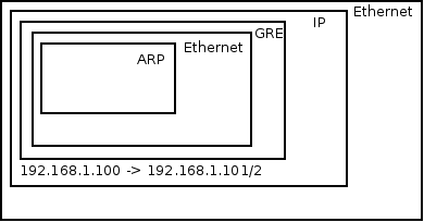
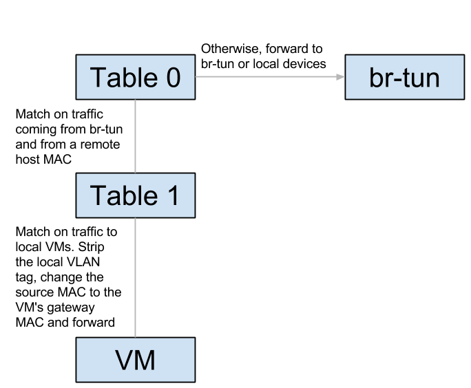
Let’s track unicast traffic from the local VM ‘blue’ on the blue subnet to a remote VM orange on the orange subnet. It will first be forwarded from the blue VM to its local gateway through br-int and arrive at the router namespace. The router will route to the remote VM’s orange subnet, effectively replacing the source MAC to its orange interface, and the destination MAC with the orange VM’s MAC (How does it know this MAC? More on this in the next section). It then sends the packet back to br-int, which forwards it again to br-tun. Upon arrival to br-tun’s table 0, the traffic is classified as traffic coming from br-int and is redirected to table 1. The source MAC at this point is the router’s orange MAC and is thus changed to the local host’s MAC and redirected to table 2. The traffic is classified as unicast traffic and is redirected to table 20, where l2pop inserted a flow for the remote VM’s orange MAC and the traffic is sent out through the appropriate tunnel with the relevant tunnel ID.
When the traffic arrives at the remote host, it is forwarded to br-tun which redirects the traffic to table 4 (Assuming VXLAN). The tunnel ID is matched and a local VLAN tag is strapped on (This is so the network could be matched when it arrives on br-int). In table 9, the host MAC of the first host is matched, and the traffic is forwarded to br-int. In br-int, the traffic is redirected to table 1 because it matches the source MAC of the first host. Finally, the local VLAN tag is stripped, the source MAC is changed again to match the router’s orange MAC and the traffic is forwarded to the orange VM. Success!
ARP
Let’s observe the ARP table of the router on the first node:
[stack@vpn-6-21 devstack (master=)]$ sudo ip netns exec qrouter-44015de0-f772-4af9-a47f-5a057b28fd72 ip neighbor
10.0.0.11 dev qr-c7fa2d36-3d lladdr fa:16:3e:19:63:25 PERMANENT
20.0.0.22 dev qr-a3bc956c-25 lladdr fa:16:3e:7d:49:80 PERMANENT
Permanent / static records, that’s curious… How’d they end up there? As it turns out, part of the process of configuring a DVR router is populating static ARP entries for every port on an interface’s subnet. This is done whenever a new router is scheduled to a L3 agent, or an interface is added to an existing router. Every relevant L3 agent receives the notification, and when adding the interface to the router (Or configuring a new router), it asks for all of the ports on the interface’s subnet via a new RPC method. It then adds a static ARP entry for every port. Whenever a new port is created, or an existing unbound port’s MAC address is changed, all L3 agents hosting a DVR router attached to the port’s subnet are notified via another new RPC method, and an ARP entry is added (Or deleted) from the relevant router.