DVR, OpenStack

Distributed Virtual Routing – Floating IPs

Where Am I?
Overview and East/West Traffic
SNAT
* Floating IPs

In The Good Old Days…

Legacy routers provide floating IPs connectivity by performing 1:1 NAT between the VM’s fixed IP and its floating IP inside the router namespace. Additionally, the L3 agent throws out a gratuitous ARP when it configures the floating IP on the router’s external device. This is done to advertise to the external network that the floating IP is reachable via the router’s external device’s MAC address. Floating IPs are configured as /32 prefixes on the router’s external device and so the router answers any ARP requests for these addresses. Legacy routers are of course scheduled only on a select subgroup of nodes known as network nodes.

Things Are About to Get Weird

In the DVR world, however, things are very different. This is going to get very complicated very fast so let’s understand how and why we got there. We could have kept things the way they are and configured floating IPs on the router’s ‘qg’ device. Or could we? Let’s consider that for a moment:

  • MAC addresses! Network engineers go to great lengths to minimize broadcast domains because networking devices have fairly modest upper bounds on their MAC tables. Most external networks use flat or VLAN networking: It is possible to subdivide them by using multiple external networks, or multiple subnets on a single external network, but let’s consider a single external network for the purpose of this discussion. With legacy routers you would ‘consume’ a MAC address on the external network per router. If we kept the existing model but distributed the routers, we would consume a MAC address for every (node, router) pair. This would quickly explode the size of the broadcast domain. Not good!
  • IP addresses! Legacy routers configure a routable address on their external devices. It’s not wasted by any means because it is used for SNAT traffic. With DVR, as we noticed in the previous blog post, we do the same. Do we actually need a dedicated router IP per compute node then? No, not really. Not for FIP NAT purposes. You might want one for troubleshooting purposes, but it’s not needed for NAT. Instead, it was chosen to allocate a dedicated IP address for every (node, external network) pair.

Where We Ended Up

Let’s jump ahead and see how everything is wired up (On compute nodes):

fip

When a floating IP is attached to a VM, the L3 agent creates a FIP namespace (If one does not already exist) for the external network that the FIP belongs to:

[stack@vpn-6-21 devstack (master=)]$ ip netns
fip-cef4f7b4-c344-4904-a847-a9960f58fb20
qrouter-ef25020f-012c-41d6-a36e-f2f09cb8ea62

As we can see the fip namespace name is determined by the ID of the external network it represents:

[stack@vpn-6-21 devstack (master=)]$ neutron net-show public
...
| id                        | cef4f7b4-c344-4904-a847-a9960f58fb20 |
...

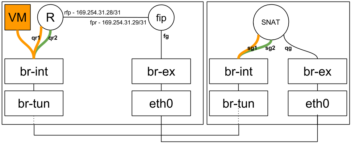
Every router on the compute node is hooked up to the FIP namespace via a veth pair (Quick reminder: A veth pair is a type of Linux networking device that is represented by a pair of devices. Whatever goes in on one end leaves via the other end. Each end of the pair may be configured with its own IP address. Veth pairs are often used to interconnect namespaces as each end of the pair may be put in a namespace of your choosing).

The ‘rfp’ or ‘router to FIP’ end of the pair resides in the router namespace:

[stack@vpn-6-21 devstack (master=)]$ sudo ip netns exec qrouter-ef25020f-012c-41d6-a36e-f2f09cb8ea62 ip address
    ...
3: rfp-ef25020f-0: <BROADCAST,MULTICAST,UP,LOWER_UP> mtu 1500 qdisc pfifo_fast state UP group default qlen 1000
    link/ether 16:91:f5:0b:34:50 brd ff:ff:ff:ff:ff:ff
    inet 169.254.31.28/31 scope global rfp-ef25020f-0
    inet 192.168.1.3/32 brd 192.168.1.3 scope global rfp-ef25020f-0
    ...
52: qr-369f59a5-2c: <BROADCAST,MULTICAST,UP,LOWER_UP> mtu 1500 qdisc noqueue state UNKNOWN group default 
    link/ether fa:16:3e:33:6d:d7 brd ff:ff:ff:ff:ff:ff
    inet 20.0.0.1/24 brd 20.0.0.255 scope global qr-369f59a5-2c
    ...
53: qr-c2e43983-5c: <BROADCAST,MULTICAST,UP,LOWER_UP> mtu 1500 qdisc noqueue state UNKNOWN group default 
    link/ether fa:16:3e:df:74:6c brd ff:ff:ff:ff:ff:ff
    inet 10.0.0.1/24 brd 10.0.0.255 scope global qr-c2e43983-5c
    ...

While the ‘fpr’ or ‘FIP to router’ end of the pair resides in the FIP namespace, along with the ‘fg’ / external device:

[stack@vpn-6-21 devstack (master=)]$ sudo ip netns exec fip-cef4f7b4-c344-4904-a847-a9960f58fb20 ip a
1: lo: <LOOPBACK,UP,LOWER_UP> mtu 65536 qdisc noqueue state UNKNOWN group default 
    ...
3: fpr-ef25020f-0: <BROADCAST,MULTICAST,UP,LOWER_UP> mtu 1500 qdisc pfifo_fast state UP group default qlen 1000
    link/ether 3e:d3:e7:34:f6:f3 brd ff:ff:ff:ff:ff:ff
    inet 169.254.31.29/31 scope global fpr-ef25020f-0
    ...
59: fg-b2b77eed-1b: <BROADCAST,MULTICAST,UP,LOWER_UP> mtu 1500 qdisc noqueue state UNKNOWN group default 
    link/ether fa:16:3e:cc:98:c8 brd ff:ff:ff:ff:ff:ff
    inet 192.168.1.23/24 brd 192.168.1.255 scope global fg-b2b77eed-1b
    ...

As you’ve surely noticed, the rfp and fpr are configured with link local IP addresses. Every time a router is configured on a compute node and hooked up to the FIP namespace in case a floating IP was configured on said router, a pair of free IP addresses is allocated out of a large pool of 169.254.x.y. These allocations are then persisted locally on the node’s disk in case the agent or the node decide to do the unthinkable and reboot.

Before we track a packet as it leaves a VM, let’s observe the routing rules in the router namespace:

[stack@vpn-6-21 devstack (master=)]$ sudo ip netns exec qrouter-ef25020f-012c-41d6-a36e-f2f09cb8ea62 ip rule
0:	from all lookup local 
32766:	from all lookup main 
32767:	from all lookup default 
32768:	from 10.0.0.4 lookup 16 
167772161:	from 10.0.0.1/24 lookup 167772161 
335544321:	from 20.0.0.1/24 lookup 335544321

Huzzah, a new source routing rule! This time it’s a specific rule with our VM’s fixed IP address. You’ll notice that it has a lower (Better) priority than the generic rules that follow. We’ll expand on this in a moment.

Tracking a Packet

In the previous blog post we talked about classifying east/west and SNAT traffic and forwarding appropriately. Today we are joined by a third traffic class: Floating IP traffic. SNAT and floating IP traffic is differentiated by the ip rules shown above. Whenever a floating IP is configured by a L3 agent it adds a rule specific to that IP: It adds the fixed IP of the VM to the rules table, and a new routing table (In this example ’16’):

[stack@vpn-6-21 devstack (master=)]$ sudo ip netns exec qrouter-ef25020f-012c-41d6-a36e-f2f09cb8ea62 ip route show table 16
default via 169.254.31.29 dev rfp-ef25020f-0

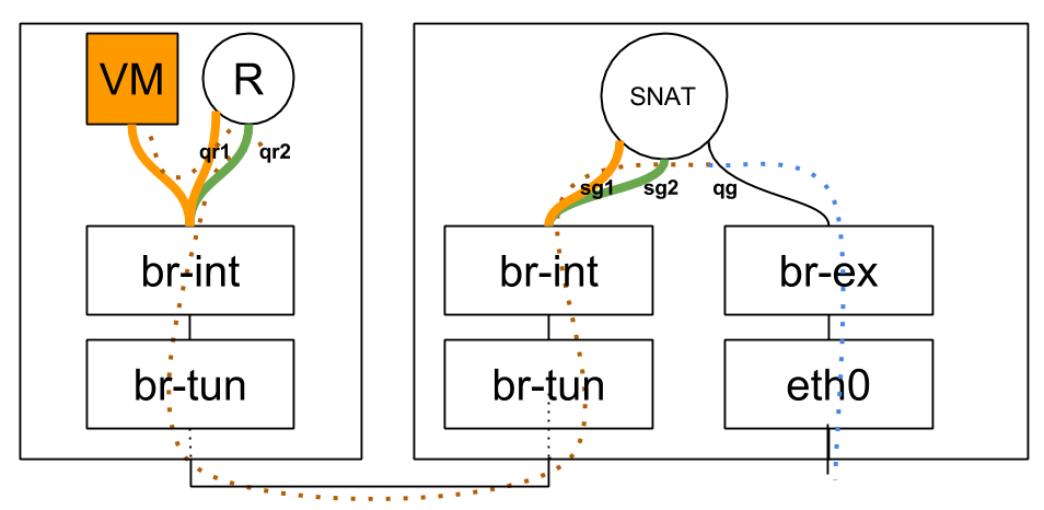
If VM 10.0.0.4 (With floating IP 192.168.1.3) sends traffic destined to the outside world, it arrives in the local qrouter namespace and the ip rules are consulted just like in the SNAT example in the previous blog post. The main routing table doesn’t have a default route, and the ‘32768:    from 10.0.0.4 lookup 16′ rule is matched. The routing table known as ’16’ has a single entry, a default route with 169.254.31.29 as the next hop. The qrouter iptables NAT rules apply and the source IP is replaced with 192.168.1.3. The message is then forwarded with 169.254.31.29’s MAC address via the rfp device, landing squarely in the FIP namespace using its ‘fpr’ device. The FIP namespace routing table has a default route, and the packet leaves through the ‘fg’ device.

The opposing direction is similar, but there’s a catch. How does the outside world know where is the VM’s floating IP address: 192.168.1.3? In fact, how does the fip namespace know where it is? It has an IP address in that subnet, but the address itself is a hop away in the qrouter namespace. To solve both problems, proxy ARP is enabled on the ‘fg’ device in the FIP namespace. This means that the FIP namespace will answer ARP requests for IP addresses that reside on its own interfaces, as well as addresses it knows how to route to. To this end, every floating IP is configured with a route from the FIP namespace back to the router’s namespace as we can see below:

[stack@vpn-6-21 devstack (master=)]$ sudo ip netns exec fip-cef4f7b4-c344-4904-a847-a9960f58fb20 ip route
default via 192.168.1.1 dev fg-b2b77eed-1b 
169.254.31.28/31 dev fpr-ef25020f-0  proto kernel  scope link  src 169.254.31.29 
192.168.1.0/24 dev fg-b2b77eed-1b  proto kernel  scope link  src 192.168.1.23 
192.168.1.3 via 169.254.31.28 dev fpr-ef25020f-0 

When the outside world wants to contact the VM’s floating IP, the FIP namespace will reply that 192.168.1.3 is available via the fg’s device MAC address (An awful lie, but a useful one… Such is the life of a proxy). The traffic will be forwarded to the machine, in through a NIC connected to br-ex and in to the FIP’s namespace ‘fg’ device. The FIP namespace will use its route to 192.168.1.3 and route it out its fpr veth device. The message will be received by the qrouter namespace: 192.168.1.3 is configured on its rfp device, its iptables rules will replace the packet’s destination IP with the VM’s fixed IP of 10.0.0.4 and off to the VM the message goes. To confuse this business even more, gratuitous ARPs are sent out just like with legacy routers. Here however, the floating IP is not actually configured on the ‘fg’ device. This is why it is configured temporarily right before the GARP is sent and removed right afterwards.

A Summary of Sorts

traffic_class

all

Standard
DVR, OpenStack

Distributed Virtual Routing – SNAT

Where Am I?
Overview and East/West Traffic
* SNAT
Floating IPs

SNAT vs Floating IPs

A quick reminder about two NAT types used in Neutron.

  1. SNAT refers to source NAT, or, changing the source address of packets as they leave the external device of a router. This is used for traffic originating from VMs that have no floating IP attached. A router is allocated a single IP address from the external network which is shared across all VMs connected to all subnets the router is connected to. Sessions are differentiated according to the full tuple of (source IP, destination IP, source port, destination port). This is typically known as ‘PAT’, or port address translation in the networking world.
  2. Floating IPs, sometimes called DNAT (Destination NAT) in Neutronland, implement a much simpler form of NAT, a 1:1 private to public address translation. You can assign a VM a floating IP and access it from the outside world.

Why Keep SNAT Centralized?

DVR distributes floating IPs north/south traffic to the compute node, just as it does for east/west traffic. This will be explained in the next blog post. SNAT north/south traffic, however, is not distributed to the compute nodes, but remains centralized on your typical network nodes. Why is this? Intuitively, you’re going to need an address from the external network on every node providing the SNAT service. This quickly becomes a matter of balance – How far would you like to distribute SNAT vs consumption of addresses on your external network(s)? The approach that was chosen is to not distribute the SNAT service at all, but keep it centralized like legacy routers. The next step would be to make the SNAT portion of distributed routers highly available by integrating DVR with L3 HA, and this work is planned for the Liberty cycle.

Logical Topology

snat_logical

Note that the router has two ports in each internal network. This is an implementation detail that you can safely ignore for now and will be explained later.

Physical Topology

snat_physical

SNAT Router Lifecycle

After attaching the router to an external network, the SNAT portion of the router is scheduled amongst L3 agents in dvr_snat mode. Observing the dvr_snat machine:

[stack@vpn-6-22 devstack (master=)]$ ip netns
snat-ef25020f-012c-41d6-a36e-f2f09cb8ea62
qrouter-ef25020f-012c-41d6-a36e-f2f09cb8ea62

We can see that two namespaces were created for the same router. The ‘regular’ qrouter namespace, which is identical to the namespace created on compute nodes and is used to service VM, DHCP or LB ports on that machine, and the ‘snat’ namespace, which is used for the centralized SNAT service. Let’s dive deeper in to this new SNAT namespace:

[stack@vpn-6-22 devstack (master=)]$ sudo ip netns exec snat-ef25020f-012c-41d6-a36e-f2f09cb8ea62 ip address
1: lo: <LOOPBACK,UP,LOWER_UP> mtu 65536 qdisc noqueue state UNKNOWN group default 
    ...
101: sg-1b9c9c26-38: <BROADCAST,MULTICAST,UP,LOWER_UP> mtu 1500 qdisc noqueue state UNKNOWN group default 
    link/ether fa:16:3e:a3:ef:a9 brd ff:ff:ff:ff:ff:ff
    inet 10.0.0.3/24 brd 10.0.0.255 scope global sg-1b9c9c26-38
    ...
102: qg-8be609d9-e3: <BROADCAST,MULTICAST,UP,LOWER_UP> mtu 1500 qdisc noqueue state UNKNOWN group default 
    link/ether fa:16:3e:93:cb:37 brd ff:ff:ff:ff:ff:ff
    inet 192.168.1.21/24 brd 192.168.1.255 scope global qg-8be609d9-e3
    ...
104: sg-fef045fb-10: <BROADCAST,MULTICAST,UP,LOWER_UP> mtu 1500 qdisc noqueue state UNKNOWN group default 
    link/ether fa:16:3e:de:85:63 brd ff:ff:ff:ff:ff:ff
    inet 20.0.0.3/24 brd 20.0.0.255 scope global sg-fef045fb-10
    ...

We can see two new ‘sg’ devices in the SNAT namespace, and the familiar ‘qg’ / external device (Which is not present in the qrouter namespces). Where did these ‘sg’ devices come from? These are additional ports, one for each internal network the router is connected to. This is why the router now has two ports in every internal network, the ‘qr’ device on compute nodes, and the ‘sg’ device in the SNAT namespace. These ‘sg’ ports are used as an extra hop during VM SNAT traffic.

Tracking a Packet

When a VM without a floating IP sends traffic destined to the outside world, it hits the qrouter namespace on its node, which redirects the message to the SNAT namespace. To achieve this, some source routing trickery is used. Here’s a concise source routing tutorial. Now that you are familiar with ‘ip rule’, the idea of multiple routing tables and source routing, let’s move on!

Let’s observe the ‘ip rule’ output executed from within the qrouter namespace on the compute node:

[stack@vpn-6-21 devstack (master=)]$ sudo ip netns exec qrouter-ef25020f-012c-41d6-a36e-f2f09cb8ea62 ip rule
0:	from all lookup local 
32766:	from all lookup main 
32767:	from all lookup default 
167772161:	from 10.0.0.1/24 lookup 167772161 
335544321:	from 20.0.0.1/24 lookup 335544321

It looks like there’s source routing rules setup for every subnet the router is attached to. Let’s look at the main routing table, as well as the new routing tables:

[stack@vpn-6-21 devstack (master=)]$ sudo ip netns exec qrouter-ef25020f-012c-41d6-a36e-f2f09cb8ea62 ip route
10.0.0.0/24 dev qr-c2e43983-5c  proto kernel  scope link  src 10.0.0.1 
20.0.0.0/24 dev qr-369f59a5-2c  proto kernel  scope link  src 20.0.0.1
[stack@vpn-6-21 devstack (master=)]$ sudo ip netns exec qrouter-ef25020f-012c-41d6-a36e-f2f09cb8ea62 ip route show table 167772161
default via 10.0.0.3 dev qr-c2e43983-5c
[stack@vpn-6-21 devstack (master=)]$ sudo ip netns exec qrouter-ef25020f-012c-41d6-a36e-f2f09cb8ea62 ip route show table 335544321
default via 20.0.0.3 dev qr-369f59a5-2c

We can observe that 10.0.0.3 and 20.0.0.3 are the ‘sg’ devices for the same router in the SNAT namespace on the dvr_snat node.

How then is east/west traffic and SNAT traffic classified and routed? If a VM in the 10.0.0.0/24 subnet on the local compute node pings a remote VM in the 20.0.0.0/24, we’d expect that to get classified as east/west traffic and go through the process explained in the previous blog post. The source guest OS puts 20.0.0.x in the destination IP and the MAC address of its default gateway in the packet and frame respectively. br-int forwards the message to the qrouter namespace on the local node, and the namespace’s ip rules are consulted. ip rules are processed according to their priority (Lowest to highest), which is listed in the first column in the ‘ip rule’ output above. The main routing table has an entry for 20.0.0.0/24 thus the message is forwarded out the appropriate ‘qr’ device.

If the same VM ping’d 8.8.8.8, however, it’d be a different story. The main routing table would be consulted first, however, it cannot match 8.8.8.8, and the main routing table doesn’t have a default route. Let’s take another look at the routing rules in place: The main routing table was consulted but did not hit a match. The ‘default’ table is empty. Can we match any of the remaining rules? Of course, the source IP address is in the 10.0.0.0/24 range, thus the fourth rule matches and the 167772161 table is consulted. We can see that it contains a single entry, a default route. The message is then routed to 10.0.0.3 (The ‘sg’ device for the subnet) via that subnet’s local ‘qr’ device. Interestingly, this is the same device the message came in on. At this point, standard DVR east/west routing takes place and the message eventually finds itself in the SNAT namespace on the dvr_snat node, where it is routed out via the ‘qg’ / external device, right after SNAT iptables rules change the source IP from the VM to the ‘qg’ device IP.

Standard
DVR, Open vSwitch, OpenStack

Distributed Virtual Routing – Overview and East/West Routing

Where Am I?
* Overview and East/West Traffic
SNAT
Floating IPs

Legacy Routing

legacy

Overview

DVR aims to isolate the failure domain of the traditional network node and to optimize network traffic by eliminating the centralized L3 agent shown above. It does that by moving most of the routing previously performed on the network node to the compute nodes.

  • East/west traffic (Traffic between different networks in the same tenant, for example between different tiers of your app) previously all went through one of your network nodes whereas with DVR it will bypass the network node, going directly between the compute nodes hosting the VMs.
  • North/south traffic with floating IPs (Traffic originating from the external network to VMs using floating IPs, or the other way around) will not go through the network node, but will be routed directly by the compute node hosting the VM. As you can understand, DVR asserts that your compute nodes are directly connected to your external network(s).
  • North/south traffic for VMs without floating IPs will still be routed through the network node (Distributing SNAT poses another set of challenges).

Each of these traffic categories introduces its own set of complexities and will be explained in separate blog posts. The following sections depicts the requirements and the previous blog post lists the required configuration changes.

Required Knowledge

Deployment Requirements

  • ML2 plugin
  • L2pop mechanism driver enabled
  • openvswitch mechanism driver enabled, and the OVS agent installed on all of your compute nodes
  • External network connectivity to each of your individual compute nodes
  • Juno required tunneling (VXLAN or GRE) tenant networks
  • Kilo introduces support for VLAN tenant networks as well

East/West Routing

Logical topology:

east_west


Physical topology:

east_west_physical_cropped

In this example, the blue VM pings the orange VM. As you can see via the dotted line, routing occurs in the source host. The router present on both compute nodes is the same router.

neutron router-list
+--------------------------------------+-------------+-----------------------+-------------+-------+
| id                                   | name        | external_gateway_info | distributed | ha    |
+--------------------------------------+-------------+-----------------------+-------------+-------+
| 44015de0-f772-4af9-a47f-5a057b28fd72 | distributed | null                  | True        | False |
+--------------------------------------+-------------+-----------------------+-------------+-------+

As we can see, the same router is present on two different compute nodes:

[stack@vpn-6-21 devstack (master=)]$ neutron l3-agent-list-hosting-router distributed
+--------------------------------------+-------------------------+----------------+-------+----------+
| id                                   | host                    | admin_state_up | alive | ha_state |
+--------------------------------------+-------------------------+----------------+-------+----------+
| 6aaeb8a4-b393-4d08-96d2-e66be23216c1 | vpn-6-23.tlv.redhat.com | True           | :-)   |          |
| e8b033c5-b515-4a95-a5ca-dbc919b739ef | vpn-6-21.tlv.redhat.com | True           | :-)   |          |
+--------------------------------------+-------------------------+----------------+-------+----------+

The router namespace was created on both nodes, and it has the exact same interfaces, MAC and IP addresses:

[stack@vpn-6-21 devstack (master=)]$ ip netns
qrouter-44015de0-f772-4af9-a47f-5a057b28fd72

[stack@vpn-6-21 devstack (master=)]$ sudo ip netns exec qrouter-44015de0-f772-4af9-a47f-5a057b28fd72 ip address
1: lo: <LOOPBACK,UP,LOWER_UP> mtu 65536 qdisc noqueue state UNKNOWN group default 
    ...
70: qr-c7fa2d36-3d: <BROADCAST,MULTICAST,UP,LOWER_UP> mtu 1500 qdisc noqueue state UNKNOWN group default 
    link/ether fa:16:3e:3c:74:9c brd ff:ff:ff:ff:ff:ff
    inet 10.0.0.1/24 brd 10.0.0.255 scope global qr-c7fa2d36-3d
    ...
71: qr-a3bc956c-25: <BROADCAST,MULTICAST,UP,LOWER_UP> mtu 1500 qdisc noqueue state UNKNOWN group default 
    link/ether fa:16:3e:a3:3b:39 brd ff:ff:ff:ff:ff:ff
    inet 20.0.0.1/24 brd 20.0.0.255 scope global qr-a3bc956c-25
    ...
[stack@vpn-6-23 devstack (master=)]$ ip netns
qrouter-44015de0-f772-4af9-a47f-5a057b28fd72

[stack@vpn-6-23 devstack (master=)]$ sudo ip netns exec qrouter-44015de0-f772-4af9-a47f-5a057b28fd72 ip address
1: lo: <LOOPBACK,UP,LOWER_UP> mtu 65536 qdisc noqueue state UNKNOWN group default 
    ...
68: qr-c7fa2d36-3d: <BROADCAST,MULTICAST,UP,LOWER_UP> mtu 1500 qdisc noqueue state UNKNOWN group default 
    link/ether fa:16:3e:3c:74:9c brd ff:ff:ff:ff:ff:ff
    inet 10.0.0.1/24 brd 10.0.0.255 scope global qr-c7fa2d36-3d
    ...
69: qr-a3bc956c-25: <BROADCAST,MULTICAST,UP,LOWER_UP> mtu 1500 qdisc noqueue state UNKNOWN group default 
    link/ether fa:16:3e:a3:3b:39 brd ff:ff:ff:ff:ff:ff
    inet 20.0.0.1/24 brd 20.0.0.255 scope global qr-a3bc956c-25
    ...

Router Lifecycle

For the purpose of east/west traffic we will happily ignore the SNAT / centralized portion of distributed routers. Since DVR routers are spawned on compute nodes, and a deployment can potentially have a great deal of them, it becomes important to optimize and create instances of DVR routers only when and where it makes sense.

  • When a DVR router is hooked up to a subnet, the router is scheduled to all compute nodes hosting ports on said subnet (This includes DHCP, LB and VM ports)
    • The L3 agent on the compute node will receive a notification and configure the router
    • The OVS agent will plug the distributed router port and configure its flows
  • When a VM (That’s connected to a subnet that is served by a DVR router) is spawned, and the VM’s compute node does not already have that DVR router configured then the router is scheduled to the node

Host MACs

Before tracking a packet from one VM to the next, let’s outline an issue with the nature of distributed ports. As we can see in the ‘ip address’ output above, DVR router replicas are scheduled to all relevant compute nodes. This means that the exact same interface (MAC and IP address included!) is present in more than one place in the network. Without taking special precautions this could result in a catastrophe.

  • When using VLAN tenant networks, the underlay hardware switches will re-learn the router’s internal devices MAC addresses again and again from different ports. This could cause issues, depending on the switch and how it is configured (Some admins enable security measures to disable re-learning a MAC on a different port by shutting down the offending port). Generally speaking, it is a fundamental networking assumption that a MAC address should only be present in one location in the network at a time.
  • Regardless of the segmentation type, the virtual switches on a given compute node would learn that the MAC address is present both locally and remotely, resulting in a similar effect as with the hardware underlay switches.

The chosen solution was to allocate a unique MAC address per compute node. When a DVR-enabled OVS agent starts, it requests its MAC address from the server via a new RPC message. If one exists, it is returned, otherwise a new address is generated, persisted in the database in a new Host MACs table and returned.

MariaDB [neutron]> select * from dvr_host_macs;
+-------------------------+-------------------+
| host                    | mac_address       |
+-------------------------+-------------------+
| vpn-6-21.tlv.redhat.com | fa:16:3f:09:34:f2 |
| vpn-6-23.tlv.redhat.com | fa:16:3f:4e:4f:98 |
| vpn-6-22.tlv.redhat.com | fa:16:3f:64:a0:74 |
+-------------------------+-------------------+

This address is then used whenever traffic from a DVR router leaves the machine; The source MAC address of the DVR interface is replaced with the host’s MAC address via OVS flows. As for the reverse, it is assumed that you may not connect more than a single router to a subnet (Which is actually an incorrect assumption as the API allows this). When traffic comes in to a compute node, and it matches a local VM’s MAC address and his network’s segmentation ID, then the source MAC is replaced from the remote machine’s host MAC to that VM’s gateway MAC.

Flows

br-int:

br-int

br-tun:

br-tun

Let’s track unicast traffic from the local VM ‘blue’ on the blue subnet to a remote VM orange on the orange subnet. It will first be forwarded from the blue VM to its local gateway through br-int and arrive at the router namespace. The router will route to the remote VM’s orange subnet, effectively replacing the source MAC to its orange interface, and the destination MAC with the orange VM’s MAC (How does it know this MAC? More on this in the next section). It then sends the packet back to br-int, which forwards it again to br-tun. Upon arrival to br-tun’s table 0, the traffic is classified as traffic coming from br-int and is redirected to table 1. The source MAC at this point is the router’s orange MAC and is thus changed to the local host’s MAC and redirected to table 2. The traffic is classified as unicast traffic and is redirected to table 20, where l2pop inserted a flow for the remote VM’s orange MAC and the traffic is sent out through the appropriate tunnel with the relevant tunnel ID.

When the traffic arrives at the remote host, it is forwarded to br-tun which redirects the traffic to table 4 (Assuming VXLAN). The tunnel ID is matched and a local VLAN tag is strapped on (This is so the network could be matched when it arrives on br-int). In table 9, the host MAC of the first host is matched, and the traffic is forwarded to br-int. In br-int, the traffic is redirected to table 1 because it matches the source MAC of the first host. Finally, the local VLAN tag is stripped, the source MAC is changed again to match the router’s orange MAC and the traffic is forwarded to the orange VM. Success!

ARP

Let’s observe the ARP table of the router on the first node:

[stack@vpn-6-21 devstack (master=)]$ sudo ip netns exec qrouter-44015de0-f772-4af9-a47f-5a057b28fd72 ip neighbor
10.0.0.11 dev qr-c7fa2d36-3d lladdr fa:16:3e:19:63:25 PERMANENT
20.0.0.22 dev qr-a3bc956c-25 lladdr fa:16:3e:7d:49:80 PERMANENT

Permanent / static records, that’s curious… How’d they end up there? As it turns out, part of the process of configuring a DVR router is populating static ARP entries for every port on an interface’s subnet. This is done whenever a new router is scheduled to a L3 agent, or an interface is added to an existing router. Every relevant L3 agent receives the notification, and when adding the interface to the router (Or configuring a new router), it asks for all of the ports on the interface’s subnet via a new RPC method. It then adds a static ARP entry for every port. Whenever a new port is created, or an existing unbound port’s MAC address is changed, all L3 agents hosting a DVR router attached to the port’s subnet are notified via another new RPC method, and an ARP entry is added (Or deleted) from the relevant router.

References

Standard
DVR, OpenStack

Multinode DVR Devstack

I recently configured a multi-node Devstack DVR setup and thought it might be useful to share my experience.

I use three VMs: 192.168.0.1/2/3. Each VM has one NIC with internet access. I normally run Devstack Neutron VMs with only one NIC – If the instances you create inside this environment require internet access, just connect the NIC to br-ex and move the IP addressing information to be-ex. I designate one VM as an ‘all-in-one’ (API servers, compute, and network), the second VM as a compute, and the third as a network node. This allows me to test DVR east-west routing (This is why I have two computes) as well as default SNAT behavior (Requires a dedicated network node / A l3 agent in ‘dvr-snat’ mode). I dislike Devstack flags/macros and prefer to configure the services myself with [post-config] sections. This soothes my control-freak nature and allows me to assert that I understand how the configuration should end up looking like.

All in one local.conf:

[[local|localrc]]
DEST=/opt/openstack
DATA_DIR=$DEST/data
LOGFILE=$DATA_DIR/logs/stack.log
SCREEN_LOGDIR=$DATA_DIR/logs
VERBOSE=False
MYSQL_PASSWORD=1
RABBIT_PASSWORD=1
SERVICE_TOKEN=1
SERVICE_PASSWORD=1
ADMIN_PASSWORD=1

disable_service n-net
enable_service neutron
enable_service q-svc
enable_service q-meta
enable_service q-agt
enable_service q-dhcp
enable_service q-l3

# TODO: Set this host's IP
HOST_IP=192.168.0.1

[[post-config|$NEUTRON_CONF]]
[DEFAULT]
router_distributed=True

[[post-config|/$Q_PLUGIN_CONF_FILE]]
[ml2]
type_drivers=flat,vlan,vxlan
tenant_network_types=vxlan
mechanism_drivers=openvswitch,l2population

[ml2_type_vxlan]
vni_ranges=1000:1999

[ovs]
local_ip=$HOST_IP

[agent]
tunnel_types=vxlan
l2_population=True
enable_distributed_routing=True

[[post-config|$Q_L3_CONF_FILE]]
[DEFAULT]
agent_mode=dvr
router_delete_namespaces=True

[[post-config|$Q_DHCP_CONF_FILE]]
[DEFAULT]
dhcp_delete_namespaces=True

Compute local.conf:

[[local|localrc]]
DEST=/opt/openstack
DATA_DIR=$DEST/data
LOGFILE=$DATA_DIR/logs/stack.log
SCREEN_LOGDIR=$DATA_DIR/logs
VERBOSE=False
MYSQL_PASSWORD=1
RABBIT_PASSWORD=1
SERVICE_TOKEN=1
SERVICE_PASSWORD=1
ADMIN_PASSWORD=1

ENABLED_SERVICES=n-cpu,neutron,n-novnc,q-agt,q-l3,q-meta

# TODO: Set this host's IP
HOST_IP=192.168.0.2

# TODO: Set the controller's IP
SERVICE_HOST=192.168.0.1
MYSQL_HOST=$SERVICE_HOST
RABBIT_HOST=$SERVICE_HOST
Q_HOST=$SERVICE_HOST
GLANCE_HOSTPORT=$SERVICE_HOST:9292

VNCSERVER_PROXYCLIENT_ADDRESS=$HOST_IP
VNCSERVER_LISTEN=0.0.0.0

[[post-config|/$Q_PLUGIN_CONF_FILE]]
[ovs]
local_ip=$HOST_IP

[agent]
tunnel_types=vxlan
l2_population=True
enable_distributed_routing=True

[[post-config|$Q_L3_CONF_FILE]]
[DEFAULT]
agent_mode=dvr
router_delete_namespaces=True

Network node local.conf:

[[local|localrc]]
DEST=/opt/openstack
DATA_DIR=$DEST/data
LOGFILE=$DATA_DIR/logs/stack.log
SCREEN_LOGDIR=$DATA_DIR/logs
VERBOSE=False
MYSQL_PASSWORD=1
RABBIT_PASSWORD=1
SERVICE_TOKEN=1
SERVICE_PASSWORD=1
ADMIN_PASSWORD=1

ENABLED_SERVICES=neutron,q-agt,q-l3,q-meta

# TODO: Set this host's IP
HOST_IP=192.168.0.3

# TODO: Set the controller's IP
SERVICE_HOST=192.168.0.1
MYSQL_HOST=$SERVICE_HOST
RABBIT_HOST=$SERVICE_HOST
GLANCE_HOSTPORT=$SERVICE_HOST:9292

[[post-config|/$Q_PLUGIN_CONF_FILE]]
[ovs]
local_ip=$HOST_IP

[agent]
tunnel_types=vxlan
l2_population=True
enable_distributed_routing=True

[[post-config|$Q_L3_CONF_FILE]]
[DEFAULT]
agent_mode=dvr_snat
router_delete_namespaces=True
Standard