
I’m giving a lightning talk in the OpenStack Vancouver Neutron design summit. It’s a 5 minute talk about testing, common pitfalls and new developments with respect to testing frameworks.
Category Archives: OpenStack
Distributed Virtual Routing – Floating IPs
Where Am I?
Overview and East/West Traffic
SNAT
* Floating IPs
In The Good Old Days…
Legacy routers provide floating IPs connectivity by performing 1:1 NAT between the VM’s fixed IP and its floating IP inside the router namespace. Additionally, the L3 agent throws out a gratuitous ARP when it configures the floating IP on the router’s external device. This is done to advertise to the external network that the floating IP is reachable via the router’s external device’s MAC address. Floating IPs are configured as /32 prefixes on the router’s external device and so the router answers any ARP requests for these addresses. Legacy routers are of course scheduled only on a select subgroup of nodes known as network nodes.
Things Are About to Get Weird
In the DVR world, however, things are very different. This is going to get very complicated very fast so let’s understand how and why we got there. We could have kept things the way they are and configured floating IPs on the router’s ‘qg’ device. Or could we? Let’s consider that for a moment:
- MAC addresses! Network engineers go to great lengths to minimize broadcast domains because networking devices have fairly modest upper bounds on their MAC tables. Most external networks use flat or VLAN networking: It is possible to subdivide them by using multiple external networks, or multiple subnets on a single external network, but let’s consider a single external network for the purpose of this discussion. With legacy routers you would ‘consume’ a MAC address on the external network per router. If we kept the existing model but distributed the routers, we would consume a MAC address for every (node, router) pair. This would quickly explode the size of the broadcast domain. Not good!
- IP addresses! Legacy routers configure a routable address on their external devices. It’s not wasted by any means because it is used for SNAT traffic. With DVR, as we noticed in the previous blog post, we do the same. Do we actually need a dedicated router IP per compute node then? No, not really. Not for FIP NAT purposes. You might want one for troubleshooting purposes, but it’s not needed for NAT. Instead, it was chosen to allocate a dedicated IP address for every (node, external network) pair.
Where We Ended Up
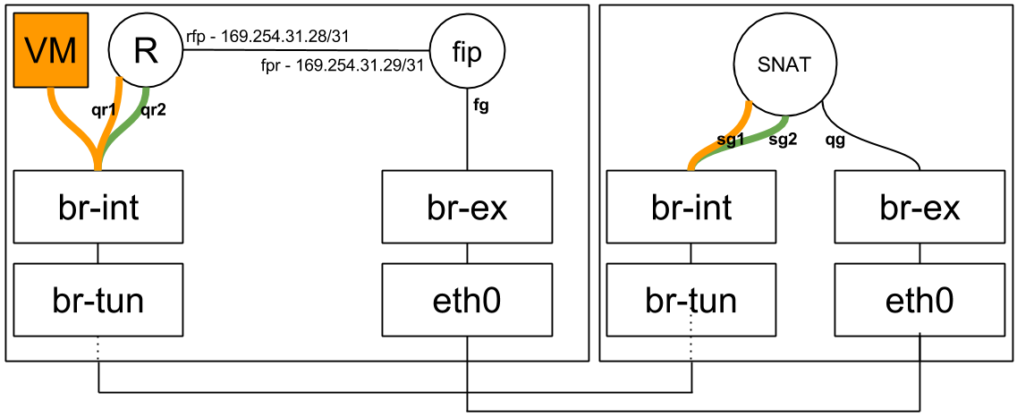
Let’s jump ahead and see how everything is wired up (On compute nodes):

When a floating IP is attached to a VM, the L3 agent creates a FIP namespace (If one does not already exist) for the external network that the FIP belongs to:
[stack@vpn-6-21 devstack (master=)]$ ip netns
fip-cef4f7b4-c344-4904-a847-a9960f58fb20
qrouter-ef25020f-012c-41d6-a36e-f2f09cb8ea62
As we can see the fip namespace name is determined by the ID of the external network it represents:
[stack@vpn-6-21 devstack (master=)]$ neutron net-show public
...
| id                        | cef4f7b4-c344-4904-a847-a9960f58fb20 |
...
Every router on the compute node is hooked up to the FIP namespace via a veth pair (Quick reminder: A veth pair is a type of Linux networking device that is represented by a pair of devices. Whatever goes in on one end leaves via the other end. Each end of the pair may be configured with its own IP address. Veth pairs are often used to interconnect namespaces as each end of the pair may be put in a namespace of your choosing).
The ‘rfp’ or ‘router to FIP’ end of the pair resides in the router namespace:
[stack@vpn-6-21 devstack (master=)]$ sudo ip netns exec qrouter-ef25020f-012c-41d6-a36e-f2f09cb8ea62 ip address
    ...
3: rfp-ef25020f-0: <BROADCAST,MULTICAST,UP,LOWER_UP> mtu 1500 qdisc pfifo_fast state UP group default qlen 1000
    link/ether 16:91:f5:0b:34:50 brd ff:ff:ff:ff:ff:ff
    inet 169.254.31.28/31 scope global rfp-ef25020f-0
    inet 192.168.1.3/32 brd 192.168.1.3 scope global rfp-ef25020f-0
    ...
52: qr-369f59a5-2c: <BROADCAST,MULTICAST,UP,LOWER_UP> mtu 1500 qdisc noqueue state UNKNOWN group default
    link/ether fa:16:3e:33:6d:d7 brd ff:ff:ff:ff:ff:ff
    inet 20.0.0.1/24 brd 20.0.0.255 scope global qr-369f59a5-2c
    ...
53: qr-c2e43983-5c: <BROADCAST,MULTICAST,UP,LOWER_UP> mtu 1500 qdisc noqueue state UNKNOWN group default
    link/ether fa:16:3e:df:74:6c brd ff:ff:ff:ff:ff:ff
    inet 10.0.0.1/24 brd 10.0.0.255 scope global qr-c2e43983-5c
    ...
While the ‘fpr’ or ‘FIP to router’ end of the pair resides in the FIP namespace, along with the ‘fg’ / external device:
[stack@vpn-6-21 devstack (master=)]$ sudo ip netns exec fip-cef4f7b4-c344-4904-a847-a9960f58fb20 ip a
1: lo: <LOOPBACK,UP,LOWER_UP> mtu 65536 qdisc noqueue state UNKNOWN group default
    ...
3: fpr-ef25020f-0: <BROADCAST,MULTICAST,UP,LOWER_UP> mtu 1500 qdisc pfifo_fast state UP group default qlen 1000
    link/ether 3e:d3:e7:34:f6:f3 brd ff:ff:ff:ff:ff:ff
    inet 169.254.31.29/31 scope global fpr-ef25020f-0
    ...
59: fg-b2b77eed-1b: <BROADCAST,MULTICAST,UP,LOWER_UP> mtu 1500 qdisc noqueue state UNKNOWN group default
    link/ether fa:16:3e:cc:98:c8 brd ff:ff:ff:ff:ff:ff
    inet 192.168.1.23/24 brd 192.168.1.255 scope global fg-b2b77eed-1b
    ...
As you’ve surely noticed, the rfp and fpr are configured with link local IP addresses. Every time a router is configured on a compute node and hooked up to the FIP namespace in case a floating IP was configured on said router, a pair of free IP addresses is allocated out of a large pool of 169.254.x.y. These allocations are then persisted locally on the node’s disk in case the agent or the node decide to do the unthinkable and reboot.
Before we track a packet as it leaves a VM, let’s observe the routing rules in the router namespace:
[stack@vpn-6-21 devstack (master=)]$ sudo ip netns exec qrouter-ef25020f-012c-41d6-a36e-f2f09cb8ea62 ip rule
0:	from all lookup local
32766:	from all lookup main
32767:	from all lookup default
32768:	from 10.0.0.4 lookup 16
167772161:	from 10.0.0.1/24 lookup 167772161
335544321:	from 20.0.0.1/24 lookup 335544321
Huzzah, a new source routing rule! This time it’s a specific rule with our VM’s fixed IP address. You’ll notice that it has a lower (Better) priority than the generic rules that follow. We’ll expand on this in a moment.
Tracking a Packet
In the previous blog post we talked about classifying east/west and SNAT traffic and forwarding appropriately. Today we are joined by a third traffic class: Floating IP traffic. SNAT and floating IP traffic is differentiated by the ip rules shown above. Whenever a floating IP is configured by a L3 agent it adds a rule specific to that IP: It adds the fixed IP of the VM to the rules table, and a new routing table (In this example ’16’):
[stack@vpn-6-21 devstack (master=)]$ sudo ip netns exec qrouter-ef25020f-012c-41d6-a36e-f2f09cb8ea62 ip route show table 16
default via 169.254.31.29 dev rfp-ef25020f-0
If VM 10.0.0.4 (With floating IP 192.168.1.3) sends traffic destined to the outside world, it arrives in the local qrouter namespace and the ip rules are consulted just like in the SNAT example in the previous blog post. The main routing table doesn’t have a default route, and the ‘32768: from 10.0.0.4 lookup 16′ rule is matched. The routing table known as ’16’ has a single entry, a default route with 169.254.31.29 as the next hop. The qrouter iptables NAT rules apply and the source IP is replaced with 192.168.1.3. The message is then forwarded with 169.254.31.29’s MAC address via the rfp device, landing squarely in the FIP namespace using its ‘fpr’ device. The FIP namespace routing table has a default route, and the packet leaves through the ‘fg’ device.
The opposing direction is similar, but there’s a catch. How does the outside world know where is the VM’s floating IP address: 192.168.1.3? In fact, how does the fip namespace know where it is? It has an IP address in that subnet, but the address itself is a hop away in the qrouter namespace. To solve both problems, proxy ARP is enabled on the ‘fg’ device in the FIP namespace. This means that the FIP namespace will answer ARP requests for IP addresses that reside on its own interfaces, as well as addresses it knows how to route to. To this end, every floating IP is configured with a route from the FIP namespace back to the router’s namespace as we can see below:
[stack@vpn-6-21 devstack (master=)]$ sudo ip netns exec fip-cef4f7b4-c344-4904-a847-a9960f58fb20 ip route
default via 192.168.1.1 dev fg-b2b77eed-1b
169.254.31.28/31 dev fpr-ef25020f-0  proto kernel  scope link  src 169.254.31.29
192.168.1.0/24 dev fg-b2b77eed-1b  proto kernel  scope link  src 192.168.1.23
192.168.1.3 via 169.254.31.28 dev fpr-ef25020f-0
When the outside world wants to contact the VM’s floating IP, the FIP namespace will reply that 192.168.1.3 is available via the fg’s device MAC address (An awful lie, but a useful one… Such is the life of a proxy). The traffic will be forwarded to the machine, in through a NIC connected to br-ex and in to the FIP’s namespace ‘fg’ device. The FIP namespace will use its route to 192.168.1.3 and route it out its fpr veth device. The message will be received by the qrouter namespace: 192.168.1.3 is configured on its rfp device, its iptables rules will replace the packet’s destination IP with the VM’s fixed IP of 10.0.0.4 and off to the VM the message goes. To confuse this business even more, gratuitous ARPs are sent out just like with legacy routers. Here however, the floating IP is not actually configured on the ‘fg’ device. This is why it is configured temporarily right before the GARP is sent and removed right afterwards.
A Summary of Sorts

Distributed Virtual Routing – SNAT
Where Am I?
Overview and East/West Traffic
* SNAT
Floating IPs
SNAT vs Floating IPs
A quick reminder about two NAT types used in Neutron.
- SNAT refers to source NAT, or, changing the source address of packets as they leave the external device of a router. This is used for traffic originating from VMs that have no floating IP attached. A router is allocated a single IP address from the external network which is shared across all VMs connected to all subnets the router is connected to. Sessions are differentiated according to the full tuple of (source IP, destination IP, source port, destination port). This is typically known as ‘PAT’, or port address translation in the networking world.
- Floating IPs, sometimes called DNAT (Destination NAT) in Neutronland, implement a much simpler form of NAT, a 1:1 private to public address translation. You can assign a VM a floating IP and access it from the outside world.
Why Keep SNAT Centralized?
DVR distributes floating IPs north/south traffic to the compute node, just as it does for east/west traffic. This will be explained in the next blog post. SNAT north/south traffic, however, is not distributed to the compute nodes, but remains centralized on your typical network nodes. Why is this? Intuitively, you’re going to need an address from the external network on every node providing the SNAT service. This quickly becomes a matter of balance – How far would you like to distribute SNAT vs consumption of addresses on your external network(s)? The approach that was chosen is to not distribute the SNAT service at all, but keep it centralized like legacy routers. The next step would be to make the SNAT portion of distributed routers highly available by integrating DVR with L3 HA, and this work is planned for the Liberty cycle.
Logical Topology
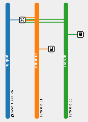
Note that the router has two ports in each internal network. This is an implementation detail that you can safely ignore for now and will be explained later.
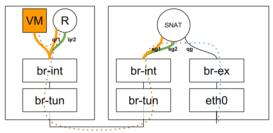
Physical Topology
SNAT Router Lifecycle
After attaching the router to an external network, the SNAT portion of the router is scheduled amongst L3 agents in dvr_snat mode. Observing the dvr_snat machine:
[stack@vpn-6-22 devstack (master=)]$ ip netns
snat-ef25020f-012c-41d6-a36e-f2f09cb8ea62
qrouter-ef25020f-012c-41d6-a36e-f2f09cb8ea62
We can see that two namespaces were created for the same router. The ‘regular’ qrouter namespace, which is identical to the namespace created on compute nodes and is used to service VM, DHCP or LB ports on that machine, and the ‘snat’ namespace, which is used for the centralized SNAT service. Let’s dive deeper in to this new SNAT namespace:
[stack@vpn-6-22 devstack (master=)]$ sudo ip netns exec snat-ef25020f-012c-41d6-a36e-f2f09cb8ea62 ip address
1: lo: <LOOPBACK,UP,LOWER_UP> mtu 65536 qdisc noqueue state UNKNOWN group default
    ...
101: sg-1b9c9c26-38: <BROADCAST,MULTICAST,UP,LOWER_UP> mtu 1500 qdisc noqueue state UNKNOWN group default
    link/ether fa:16:3e:a3:ef:a9 brd ff:ff:ff:ff:ff:ff
    inet 10.0.0.3/24 brd 10.0.0.255 scope global sg-1b9c9c26-38
    ...
102: qg-8be609d9-e3: <BROADCAST,MULTICAST,UP,LOWER_UP> mtu 1500 qdisc noqueue state UNKNOWN group default
    link/ether fa:16:3e:93:cb:37 brd ff:ff:ff:ff:ff:ff
    inet 192.168.1.21/24 brd 192.168.1.255 scope global qg-8be609d9-e3
    ...
104: sg-fef045fb-10: <BROADCAST,MULTICAST,UP,LOWER_UP> mtu 1500 qdisc noqueue state UNKNOWN group default
    link/ether fa:16:3e:de:85:63 brd ff:ff:ff:ff:ff:ff
    inet 20.0.0.3/24 brd 20.0.0.255 scope global sg-fef045fb-10
    ...
We can see two new ‘sg’ devices in the SNAT namespace, and the familiar ‘qg’ / external device (Which is not present in the qrouter namespces). Where did these ‘sg’ devices come from? These are additional ports, one for each internal network the router is connected to. This is why the router now has two ports in every internal network, the ‘qr’ device on compute nodes, and the ‘sg’ device in the SNAT namespace. These ‘sg’ ports are used as an extra hop during VM SNAT traffic.
Tracking a Packet
When a VM without a floating IP sends traffic destined to the outside world, it hits the qrouter namespace on its node, which redirects the message to the SNAT namespace. To achieve this, some source routing trickery is used. Here’s a concise source routing tutorial. Now that you are familiar with ‘ip rule’, the idea of multiple routing tables and source routing, let’s move on!
Let’s observe the ‘ip rule’ output executed from within the qrouter namespace on the compute node:
[stack@vpn-6-21 devstack (master=)]$ sudo ip netns exec qrouter-ef25020f-012c-41d6-a36e-f2f09cb8ea62 ip rule
0:	from all lookup local
32766:	from all lookup main
32767:	from all lookup default
167772161:	from 10.0.0.1/24 lookup 167772161
335544321:	from 20.0.0.1/24 lookup 335544321
It looks like there’s source routing rules setup for every subnet the router is attached to. Let’s look at the main routing table, as well as the new routing tables:
[stack@vpn-6-21 devstack (master=)]$ sudo ip netns exec qrouter-ef25020f-012c-41d6-a36e-f2f09cb8ea62 ip route
10.0.0.0/24 dev qr-c2e43983-5c  proto kernel  scope link  src 10.0.0.1
20.0.0.0/24 dev qr-369f59a5-2c  proto kernel  scope link  src 20.0.0.1
[stack@vpn-6-21 devstack (master=)]$ sudo ip netns exec qrouter-ef25020f-012c-41d6-a36e-f2f09cb8ea62 ip route show table 167772161
default via 10.0.0.3 dev qr-c2e43983-5c
[stack@vpn-6-21 devstack (master=)]$ sudo ip netns exec qrouter-ef25020f-012c-41d6-a36e-f2f09cb8ea62 ip route show table 335544321
default via 20.0.0.3 dev qr-369f59a5-2c
We can observe that 10.0.0.3 and 20.0.0.3 are the ‘sg’ devices for the same router in the SNAT namespace on the dvr_snat node.
How then is east/west traffic and SNAT traffic classified and routed? If a VM in the 10.0.0.0/24 subnet on the local compute node pings a remote VM in the 20.0.0.0/24, we’d expect that to get classified as east/west traffic and go through the process explained in the previous blog post. The source guest OS puts 20.0.0.x in the destination IP and the MAC address of its default gateway in the packet and frame respectively. br-int forwards the message to the qrouter namespace on the local node, and the namespace’s ip rules are consulted. ip rules are processed according to their priority (Lowest to highest), which is listed in the first column in the ‘ip rule’ output above. The main routing table has an entry for 20.0.0.0/24 thus the message is forwarded out the appropriate ‘qr’ device.
If the same VM ping’d 8.8.8.8, however, it’d be a different story. The main routing table would be consulted first, however, it cannot match 8.8.8.8, and the main routing table doesn’t have a default route. Let’s take another look at the routing rules in place: The main routing table was consulted but did not hit a match. The ‘default’ table is empty. Can we match any of the remaining rules? Of course, the source IP address is in the 10.0.0.0/24 range, thus the fourth rule matches and the 167772161 table is consulted. We can see that it contains a single entry, a default route. The message is then routed to 10.0.0.3 (The ‘sg’ device for the subnet) via that subnet’s local ‘qr’ device. Interestingly, this is the same device the message came in on. At this point, standard DVR east/west routing takes place and the message eventually finds itself in the SNAT namespace on the dvr_snat node, where it is routed out via the ‘qg’ / external device, right after SNAT iptables rules change the source IP from the VM to the ‘qg’ device IP.
Distributed Virtual Routing – Overview and East/West Routing
Where Am I?
* Overview and East/West Traffic
SNAT
Floating IPs
Legacy Routing

Overview
DVR aims to isolate the failure domain of the traditional network node and to optimize network traffic by eliminating the centralized L3 agent shown above. It does that by moving most of the routing previously performed on the network node to the compute nodes.
- East/west traffic (Traffic between different networks in the same tenant, for example between different tiers of your app) previously all went through one of your network nodes whereas with DVR it will bypass the network node, going directly between the compute nodes hosting the VMs.
- North/south traffic with floating IPs (Traffic originating from the external network to VMs using floating IPs, or the other way around) will not go through the network node, but will be routed directly by the compute node hosting the VM. As you can understand, DVR asserts that your compute nodes are directly connected to your external network(s).
- North/south traffic for VMs without floating IPs will still be routed through the network node (Distributing SNAT poses another set of challenges).
Each of these traffic categories introduces its own set of complexities and will be explained in separate blog posts. The following sections depicts the requirements and the previous blog post lists the required configuration changes.
Required Knowledge
- Specific sections require OVS flows and tunneling knowledge, which you can obtain from previous posts in my blog (Go from the bottom to the top)
- How ‘legacy’ (Non-distributed, non-HA) routers work
Deployment Requirements
- ML2 plugin
- L2pop mechanism driver enabled
- openvswitch mechanism driver enabled, and the OVS agent installed on all of your compute nodes
- External network connectivity to each of your individual compute nodes
- Juno required tunneling (VXLAN or GRE) tenant networks
- Kilo introduces support for VLAN tenant networks as well
East/West Routing
Logical topology:
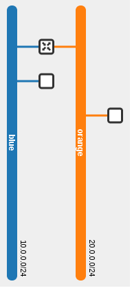
Physical topology:

In this example, the blue VM pings the orange VM. As you can see via the dotted line, routing occurs in the source host. The router present on both compute nodes is the same router.
neutron router-list
+--------------------------------------+-------------+-----------------------+-------------+-------+
| id                                   | name        | external_gateway_info | distributed | ha    |
+--------------------------------------+-------------+-----------------------+-------------+-------+
| 44015de0-f772-4af9-a47f-5a057b28fd72 | distributed | null                  | True        | False |
+--------------------------------------+-------------+-----------------------+-------------+-------+
As we can see, the same router is present on two different compute nodes:
[stack@vpn-6-21 devstack (master=)]$ neutron l3-agent-list-hosting-router distributed
+--------------------------------------+-------------------------+----------------+-------+----------+
| id                                   | host                    | admin_state_up | alive | ha_state |
+--------------------------------------+-------------------------+----------------+-------+----------+
| 6aaeb8a4-b393-4d08-96d2-e66be23216c1 | vpn-6-23.tlv.redhat.com | True           | :-)   |          |
| e8b033c5-b515-4a95-a5ca-dbc919b739ef | vpn-6-21.tlv.redhat.com | True           | :-)   |          |
+--------------------------------------+-------------------------+----------------+-------+----------+
The router namespace was created on both nodes, and it has the exact same interfaces, MAC and IP addresses:
[stack@vpn-6-21 devstack (master=)]$ ip netns
qrouter-44015de0-f772-4af9-a47f-5a057b28fd72

[stack@vpn-6-21 devstack (master=)]$ sudo ip netns exec qrouter-44015de0-f772-4af9-a47f-5a057b28fd72 ip address
1: lo: <LOOPBACK,UP,LOWER_UP> mtu 65536 qdisc noqueue state UNKNOWN group default
    ...
70: qr-c7fa2d36-3d: <BROADCAST,MULTICAST,UP,LOWER_UP> mtu 1500 qdisc noqueue state UNKNOWN group default
    link/ether fa:16:3e:3c:74:9c brd ff:ff:ff:ff:ff:ff
    inet 10.0.0.1/24 brd 10.0.0.255 scope global qr-c7fa2d36-3d
    ...
71: qr-a3bc956c-25: <BROADCAST,MULTICAST,UP,LOWER_UP> mtu 1500 qdisc noqueue state UNKNOWN group default
    link/ether fa:16:3e:a3:3b:39 brd ff:ff:ff:ff:ff:ff
    inet 20.0.0.1/24 brd 20.0.0.255 scope global qr-a3bc956c-25
    ...
[stack@vpn-6-23 devstack (master=)]$ ip netns
qrouter-44015de0-f772-4af9-a47f-5a057b28fd72

[stack@vpn-6-23 devstack (master=)]$ sudo ip netns exec qrouter-44015de0-f772-4af9-a47f-5a057b28fd72 ip address
1: lo: <LOOPBACK,UP,LOWER_UP> mtu 65536 qdisc noqueue state UNKNOWN group default
    ...
68: qr-c7fa2d36-3d: <BROADCAST,MULTICAST,UP,LOWER_UP> mtu 1500 qdisc noqueue state UNKNOWN group default
    link/ether fa:16:3e:3c:74:9c brd ff:ff:ff:ff:ff:ff
    inet 10.0.0.1/24 brd 10.0.0.255 scope global qr-c7fa2d36-3d
    ...
69: qr-a3bc956c-25: <BROADCAST,MULTICAST,UP,LOWER_UP> mtu 1500 qdisc noqueue state UNKNOWN group default
    link/ether fa:16:3e:a3:3b:39 brd ff:ff:ff:ff:ff:ff
    inet 20.0.0.1/24 brd 20.0.0.255 scope global qr-a3bc956c-25
    ...
Router Lifecycle
For the purpose of east/west traffic we will happily ignore the SNAT / centralized portion of distributed routers. Since DVR routers are spawned on compute nodes, and a deployment can potentially have a great deal of them, it becomes important to optimize and create instances of DVR routers only when and where it makes sense.
- When a DVR router is hooked up to a subnet, the router is scheduled to all compute nodes hosting ports on said subnet (This includes DHCP, LB and VM ports)
- The L3 agent on the compute node will receive a notification and configure the router
- The OVS agent will plug the distributed router port and configure its flows
- When a VM (That’s connected to a subnet that is served by a DVR router) is spawned, and the VM’s compute node does not already have that DVR router configured then the router is scheduled to the node
Host MACs
Before tracking a packet from one VM to the next, let’s outline an issue with the nature of distributed ports. As we can see in the ‘ip address’ output above, DVR router replicas are scheduled to all relevant compute nodes. This means that the exact same interface (MAC and IP address included!) is present in more than one place in the network. Without taking special precautions this could result in a catastrophe.
- When using VLAN tenant networks, the underlay hardware switches will re-learn the router’s internal devices MAC addresses again and again from different ports. This could cause issues, depending on the switch and how it is configured (Some admins enable security measures to disable re-learning a MAC on a different port by shutting down the offending port). Generally speaking, it is a fundamental networking assumption that a MAC address should only be present in one location in the network at a time.
- Regardless of the segmentation type, the virtual switches on a given compute node would learn that the MAC address is present both locally and remotely, resulting in a similar effect as with the hardware underlay switches.
The chosen solution was to allocate a unique MAC address per compute node. When a DVR-enabled OVS agent starts, it requests its MAC address from the server via a new RPC message. If one exists, it is returned, otherwise a new address is generated, persisted in the database in a new Host MACs table and returned.
MariaDB [neutron]> select * from dvr_host_macs;
+-------------------------+-------------------+
| host                    | mac_address       |
+-------------------------+-------------------+
| vpn-6-21.tlv.redhat.com | fa:16:3f:09:34:f2 |
| vpn-6-23.tlv.redhat.com | fa:16:3f:4e:4f:98 |
| vpn-6-22.tlv.redhat.com | fa:16:3f:64:a0:74 |
+-------------------------+-------------------+
This address is then used whenever traffic from a DVR router leaves the machine; The source MAC address of the DVR interface is replaced with the host’s MAC address via OVS flows. As for the reverse, it is assumed that you may not connect more than a single router to a subnet (Which is actually an incorrect assumption as the API allows this). When traffic comes in to a compute node, and it matches a local VM’s MAC address and his network’s segmentation ID, then the source MAC is replaced from the remote machine’s host MAC to that VM’s gateway MAC.
Flows
br-int:
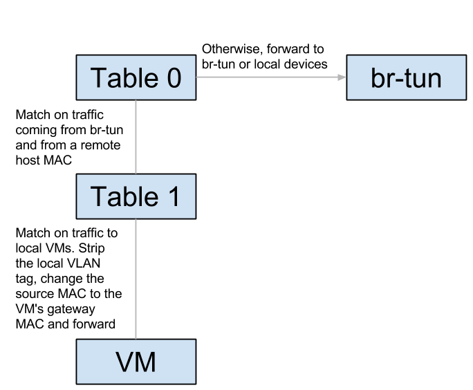
br-tun:

Let’s track unicast traffic from the local VM ‘blue’ on the blue subnet to a remote VM orange on the orange subnet. It will first be forwarded from the blue VM to its local gateway through br-int and arrive at the router namespace. The router will route to the remote VM’s orange subnet, effectively replacing the source MAC to its orange interface, and the destination MAC with the orange VM’s MAC (How does it know this MAC? More on this in the next section). It then sends the packet back to br-int, which forwards it again to br-tun. Upon arrival to br-tun’s table 0, the traffic is classified as traffic coming from br-int and is redirected to table 1. The source MAC at this point is the router’s orange MAC and is thus changed to the local host’s MAC and redirected to table 2. The traffic is classified as unicast traffic and is redirected to table 20, where l2pop inserted a flow for the remote VM’s orange MAC and the traffic is sent out through the appropriate tunnel with the relevant tunnel ID.
When the traffic arrives at the remote host, it is forwarded to br-tun which redirects the traffic to table 4 (Assuming VXLAN). The tunnel ID is matched and a local VLAN tag is strapped on (This is so the network could be matched when it arrives on br-int). In table 9, the host MAC of the first host is matched, and the traffic is forwarded to br-int. In br-int, the traffic is redirected to table 1 because it matches the source MAC of the first host. Finally, the local VLAN tag is stripped, the source MAC is changed again to match the router’s orange MAC and the traffic is forwarded to the orange VM. Success!
ARP
Let’s observe the ARP table of the router on the first node:
[stack@vpn-6-21 devstack (master=)]$ sudo ip netns exec qrouter-44015de0-f772-4af9-a47f-5a057b28fd72 ip neighbor
10.0.0.11 dev qr-c7fa2d36-3d lladdr fa:16:3e:19:63:25 PERMANENT
20.0.0.22 dev qr-a3bc956c-25 lladdr fa:16:3e:7d:49:80 PERMANENT
Permanent / static records, that’s curious… How’d they end up there? As it turns out, part of the process of configuring a DVR router is populating static ARP entries for every port on an interface’s subnet. This is done whenever a new router is scheduled to a L3 agent, or an interface is added to an existing router. Every relevant L3 agent receives the notification, and when adding the interface to the router (Or configuring a new router), it asks for all of the ports on the interface’s subnet via a new RPC method. It then adds a static ARP entry for every port. Whenever a new port is created, or an existing unbound port’s MAC address is changed, all L3 agents hosting a DVR router attached to the port’s subnet are notified via another new RPC method, and an ARP entry is added (Or deleted) from the relevant router.
References
Multinode DVR Devstack
I recently configured a multi-node Devstack DVR setup and thought it might be useful to share my experience.
I use three VMs: 192.168.0.1/2/3. Each VM has one NIC with internet access. I normally run Devstack Neutron VMs with only one NIC – If the instances you create inside this environment require internet access, just connect the NIC to br-ex and move the IP addressing information to be-ex. I designate one VM as an ‘all-in-one’ (API servers, compute, and network), the second VM as a compute, and the third as a network node. This allows me to test DVR east-west routing (This is why I have two computes) as well as default SNAT behavior (Requires a dedicated network node / A l3 agent in ‘dvr-snat’ mode). I dislike Devstack flags/macros and prefer to configure the services myself with [post-config] sections. This soothes my control-freak nature and allows me to assert that I understand how the configuration should end up looking like.
All in one local.conf:
[[local|localrc]]
DEST=/opt/openstack
DATA_DIR=$DEST/data
LOGFILE=$DATA_DIR/logs/stack.log
SCREEN_LOGDIR=$DATA_DIR/logs
VERBOSE=False
MYSQL_PASSWORD=1
RABBIT_PASSWORD=1
SERVICE_TOKEN=1
SERVICE_PASSWORD=1
ADMIN_PASSWORD=1

disable_service n-net
enable_service neutron
enable_service q-svc
enable_service q-meta
enable_service q-agt
enable_service q-dhcp
enable_service q-l3

# TODO: Set this host's IP
HOST_IP=192.168.0.1

[[post-config|$NEUTRON_CONF]]
[DEFAULT]
router_distributed=True

[[post-config|/$Q_PLUGIN_CONF_FILE]]
[ml2]
type_drivers=flat,vlan,vxlan
tenant_network_types=vxlan
mechanism_drivers=openvswitch,l2population

[ml2_type_vxlan]
vni_ranges=1000:1999

[ovs]
local_ip=$HOST_IP

[agent]
tunnel_types=vxlan
l2_population=True
enable_distributed_routing=True

[[post-config|$Q_L3_CONF_FILE]]
[DEFAULT]
agent_mode=dvr
router_delete_namespaces=True

[[post-config|$Q_DHCP_CONF_FILE]]
[DEFAULT]
dhcp_delete_namespaces=True
Compute local.conf:
[[local|localrc]]
DEST=/opt/openstack
DATA_DIR=$DEST/data
LOGFILE=$DATA_DIR/logs/stack.log
SCREEN_LOGDIR=$DATA_DIR/logs
VERBOSE=False
MYSQL_PASSWORD=1
RABBIT_PASSWORD=1
SERVICE_TOKEN=1
SERVICE_PASSWORD=1
ADMIN_PASSWORD=1

ENABLED_SERVICES=n-cpu,neutron,n-novnc,q-agt,q-l3,q-meta

# TODO: Set this host's IP
HOST_IP=192.168.0.2

# TODO: Set the controller's IP
SERVICE_HOST=192.168.0.1
MYSQL_HOST=$SERVICE_HOST
RABBIT_HOST=$SERVICE_HOST
Q_HOST=$SERVICE_HOST
GLANCE_HOSTPORT=$SERVICE_HOST:9292

VNCSERVER_PROXYCLIENT_ADDRESS=$HOST_IP
VNCSERVER_LISTEN=0.0.0.0

[[post-config|/$Q_PLUGIN_CONF_FILE]]
[ovs]
local_ip=$HOST_IP

[agent]
tunnel_types=vxlan
l2_population=True
enable_distributed_routing=True

[[post-config|$Q_L3_CONF_FILE]]
[DEFAULT]
agent_mode=dvr
router_delete_namespaces=True
Network node local.conf:
[[local|localrc]]
DEST=/opt/openstack
DATA_DIR=$DEST/data
LOGFILE=$DATA_DIR/logs/stack.log
SCREEN_LOGDIR=$DATA_DIR/logs
VERBOSE=False
MYSQL_PASSWORD=1
RABBIT_PASSWORD=1
SERVICE_TOKEN=1
SERVICE_PASSWORD=1
ADMIN_PASSWORD=1

ENABLED_SERVICES=neutron,q-agt,q-l3,q-meta

# TODO: Set this host's IP
HOST_IP=192.168.0.3

# TODO: Set the controller's IP
SERVICE_HOST=192.168.0.1
MYSQL_HOST=$SERVICE_HOST
RABBIT_HOST=$SERVICE_HOST
GLANCE_HOSTPORT=$SERVICE_HOST:9292

[[post-config|/$Q_PLUGIN_CONF_FILE]]
[ovs]
local_ip=$HOST_IP

[agent]
tunnel_types=vxlan
l2_population=True
enable_distributed_routing=True

[[post-config|$Q_L3_CONF_FILE]]
[DEFAULT]
agent_mode=dvr_snat
router_delete_namespaces=True
Juno Advanced Routing Compatibility
Juno has introduced two new Neutron, routing related features: High availability of virtual routers, and distributed routing.
L3 HA is not compatible with L2pop and DVR.
DVR is not compatible with L3 HA and VLANs, but requires tunneling, L2pop and compute node external network connectivity.
Confused? So am I!
Here’s where we are now:
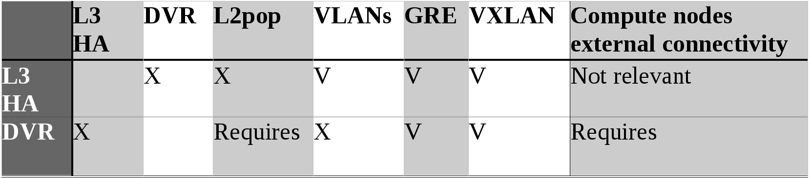
V – Compatible, X – Incompatible
And here’s what the community hopes to achieve for the next couple of releases:
- Integrate L3 HA with L2pop
- Integrate L3 HA with DVR
- Integrate DVR with VLANs
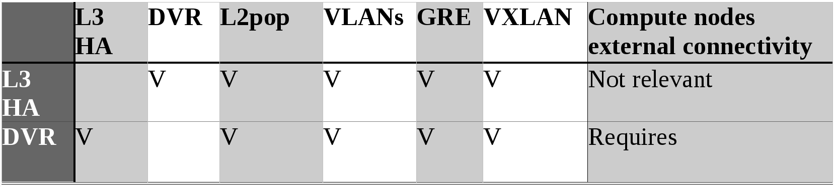
V – Compatible, X – Incompatible
Layer 3 High Availability
L3 Agent Low Availability
Today, you can utilize multiple network nodes to achieve load sharing, but not high availability or redundancy. Assuming three network nodes, creation of new routers will be scheduled and distributed amongst those three nodes. However, if a node drops, all routers on that node will cease to exist as well as any traffic normally forwarded by those routers. Neutron, in the Icehouse release, doesn’t support any built-in solution.
A Detour to the DHCP Agent
DHCP agents are a different beast altogether – The DHCP protocol allows for the co-existence of multiple DHCP servers all serving the same pool, at the same time.
By changing:
neutron.conf:
dhcp_agents_per_network = X
You will change the DHCP scheduler to schedule X DHCP agents per network. So, for a deployment with 3 network nodes, and setting dhcp_agents_per_network to 2, every Neutron network will be served by 2 DHCP agents out of 3. How does this work?
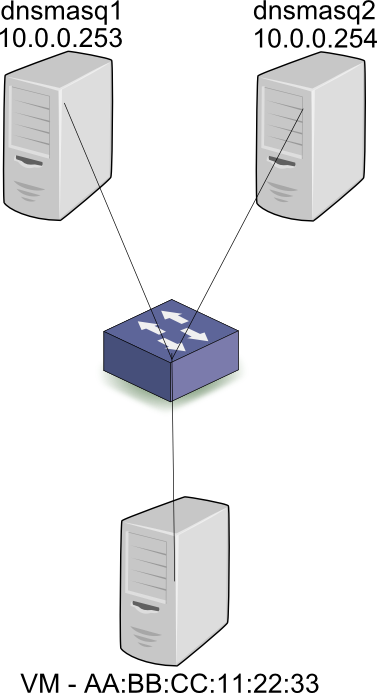
First, let’s take a look at the story from a baremetal perspective, outside of the cloud world. When the workstation is connected to a subnet in the 10.0.0.0/24 subnet, it broadcasts a DHCP discover. Both DHCP servers dnsmasq1 and dnsmasq2 (Or other implementations of a DHCP server) receive the broadcast and respond with an offer for 10.0.0.2. Assuming that the first server’s response was received by the workstation first, it will then broadcast a request for 10.0.0.2, and specify the IP address of dnsmasq1 – 10.0.0.253. Both servers receive the broadcast, but only dnsmasq1 responds with an ACK. Since all DHCP communication is via broadcasts, server 2 also receives the ACK, and can mark 10.0.0.2 as taken by AA:BB:CC:11:22:33, so as to not offer it to other workstations. To summarize, all communication between clients and servers is done via broadcasts and thus the state (What IPs are used at any given time, and by who) can be distributed across the servers correctly.
In the Neutron case, the assignment from MAC to IP is configured on each dnsmasq server beforehand, when the Neutron port is created. Thus, both dnsmasq leases file will hold the AA:BB:CC:11:22:33 to 10.0.0.2 mapping before the DHCP request is even broadcast. As you can see, DHCP HA is supported at the protocol level.
Back to the Lowly Available L3 Agent
L3 agents don’t (Currently) have any of these fancy tricks that DHCP offers, and yet the people demand high availability. So what are the people doing?
- Pacemaker / Corosync – Use external clustering technologies to specify a standby network node for an active one. The standby node will essentially sit there looking pretty, and when a failure is detected with the active node, the L3 agent will be started on the standby node. The two nodes are configured with the same hostname so that when the secondary agent goes live and synchronizes with the server, it identifies itself with the same ID and thus manages the same routers.
- Another type of solution writes a script that runs as a cron job. This would be a Python SDK script that would use the API to get a list of dead agents, get all the routers on that agent, and reschedule them to other agents.
- In the Juno time frame, look for this patch https://review.openstack.org/#/c/110893/ by Kevin Benton to bake rescheduling into Neutron itself.
Rescheduling Routers Takes a Long, Long Time
All solutions listed suffer from a substantial failover time, if only for the simple fact that configuring a non-trivial amount of routers on the new node(s) takes quite a while. Thousands of routers take hours to finish the rescheduling and configuration process. The people demand fast failover!
Distributed Virtual Router
DVR has multiple documents explaining how it works:
- http://specs.openstack.org/openstack/neutron-specs/specs/juno/neutron-ovs-dvr.html
- https://docs.google.com/document/d/1jCmraZGirmXq5V1MtRqhjdZCbUfiwBhRkUjDXGt5QUQ/
- https://docs.google.com/document/d/1depasJSnGZPOnRLxEC_PYsVLcGVFXZLqP52RFTe21BE/
The gist is that it moves routing to the compute nodes, rendering the L3 agent on the network nodes pointless. Or does it?
- DVR handles only floating IPs, leaving SNAT to the L3 agents on the network nodes
- Doesn’t work with VLANs, only works with tunnels and L2pop enabled
- Requires external connectivity on every compute node
- Generally speaking, is a significant departure from Havana or Icehouse Neutron based clouds, while L3 HA is a simpler change to make for your deployment
Ideally you would use DVR together with L3 HA. Floating IP traffic would be routed directly by your compute nodes, while SNAT traffic would go through the HA L3 agents on the network nodes.
Layer 3 High Availability
The Juno targeted L3 HA solution uses the popular Linux keepalived tool, which uses VRRP internally. First, then, let’s discuss VRRP.
What is VRRP, how does it work in the physical world?
Virtual Router Redundancy Protocol is a first hop redundancy protocol – It aims to provide high availability of the network’s default gateway, or the next hop of a route. What problem does it solve? In a network topology with two routers providing internet connectivity, you could assign half of the network’s default gateway to the first router’s IP address, and the other half to the second router.

This would provide load sharing, but what happens if one router loses connectivity? Herein comes the idea of a virtual IP address, or a floating address, which will be configured as the network’s default gateway. During a failover, the standby routers won’t receive VRRP hello messages from the master and will thus perform an election process, with the winning router acting as the active gateway, and the others remain as standby. The active router configures the virtual IP address (Or VIP for short), on its internal, LAN facing interface, and responds to ARP requests with a virtual MAC address. The network computers already have entries in their ARP caches (For the VIP + virtual MAC address) and have no reason to resend an ARP request. Following the election process, the virtuous standby router becomes the new active instance, and sends a gratuitous ARP request – Proclaiming to the network that the VIP + MAC pair now belong to it. The switches comprising the network move the virtual MAC address from the old port to the new.

By doing so, traffic to the default gateway will reach the correct (New) active router. Note that this approach does not accomplish load sharing, in the sense that all traffic is forwarded through the active router. (Note that in the Neutron use case, load sharing is not accomplished at the individual router level, but at the node level, assuming a non-trivial amount of routers). How does one accomplish load sharing at the router resolution? VRRP groups: The VRRP header includes a Virtual Router Identifier, or VRID. Half of the network hosts will configure the first VIP, and the other half the second. In the case of a failure, the VIP previously found on the failing router will transfer to another one.

The observant reader will have identified a problem – What if the active router loses connectivity to the internet? Will it remain as the active router, unable to route packets? VRRP adds the capability to monitor the external link and relinquish its role as the active router in case of a failure.
Note: As far as IP addressing goes, it’s possible to operate in two modes:
- Each router gets an IP address, regardless of its VRRP state. The master router is configured with the VIP as an additional or secondary address.
- Only the VIP is configured. IE: The master router will hold the VIP while the slaves will have no IPs configured whatsoever.
VRRP – The Dry Facts
- Encapsulated directly in the IP protocol
- Active instance uses multicast address 224.0.0.18, MAC 01-00-5E-00-00-12 when sending hello messages to its standby routers
- The virtual MAC address is of the form: 00-00-5E-00-01-{VRID}, thus only 256 different VRIDs (0 to 255) can exist in a single broadcast domain
- The election process uses a user configurable priority, from 1 to 255, the higher the better
- Preemptive elections, like in other network protocols, means that if a standby is configured with a higher priority, or comes back after losing its connectivity (And previously acting as the active instance) it will resume its role as the active router
- Non-preemptive elections mean that when an active router loses its connectivity and comes back up, it will remain in a standby role
- The hello internal is configurable (Say: Every T seconds), and standby routers perform an election process if they haven’t received a hello message from the master after 3T seconds
Back to Neutron-land
L3 HA starts a keepalived instance in every router namespace. The different router instances talk to one another via a dedicated HA network, one per tenant. This network is created under the blank tenant to hide it from the CLI and GUI. The HA network is a Neutron tenant network, same as every other network, and uses the default segmentation technology. HA routers have an ‘HA’ device in their namespace: When a HA router is created, it is scheduled to a number of network nodes, along with a port per network node, belonging to the tenant’s HA network. keepalived traffic is forwarded through the HA device (As specified in the keepalived.conf file used by the keepalived instance in the router namespace). Here’s the output of ‘ip address’ in the router namespace:
[stack@vpn-6-88 ~]$ sudo ip netns exec qrouter-b30064f9-414e-4c98-ab42-646197c74020 ip address
1: lo: <LOOPBACK,UP,LOWER_UP> mtu 65536 qdisc noqueue state UNKNOWN group default
    ...
2794: ha-45249562-ec: <BROADCAST,MULTICAST,UP,LOWER_UP> mtu 1500 qdisc noqueue state UNKNOWN group default
    link/ether 12:34:56:78:2b:5d brd ff:ff:ff:ff:ff:ff
    inet 169.254.0.2/24 brd 169.254.0.255 scope global ha-54b92d86-4f
       valid_lft forever preferred_lft forever
    inet6 fe80::1034:56ff:fe78:2b5d/64 scope link
       valid_lft forever preferred_lft forever
2795: qr-dc9d93c6-e2: <BROADCAST,MULTICAST,UP,LOWER_UP> mtu 1500 qdisc noqueue state UNKNOWN group default
    link/ether ca:fe:de:ad:be:ef brd ff:ff:ff:ff:ff:ff
    inet 10.0.0.1/24 scope global qr-0d51eced-0f
       valid_lft forever preferred_lft forever
    inet6 fe80::c8fe:deff:fead:beef/64 scope link
       valid_lft forever preferred_lft forever
2796: qg-843de7e6-8f: <BROADCAST,MULTICAST,UP,LOWER_UP> mtu 1500 qdisc noqueue state UNKNOWN group default
    link/ether ca:fe:de:ad:be:ef brd ff:ff:ff:ff:ff:ff
    inet 19.4.4.4/24 scope global qg-75688938-8d
       valid_lft forever preferred_lft forever
    inet6 fe80::c8fe:deff:fead:beef/64 scope link
       valid_lft forever preferred_lft forever
That is the output for the master instance. The same router on another node would have no IP address on the ha, qr, or qg devices. It would have no floating IPs or routing entries. These are persisted as configuration values in keepalived.conf, and when keepalived detects the master instance failing, these addresses (Or: VIPs) are configured by keepalived on the appropriate devices. Here’s an example of keepalived.conf, for the same router shown above:
vrrp_sync_group VG_1 {
    group {
        VR_1
    }
    notify_backup "/path/to/notify_backup.sh"
    notify_master "/path/to/notify_master.sh"
    notify_fault "/path/to/notify_fault.sh"
}
vrrp_instance VR_1 {
    state BACKUP
    interface ha-45249562-ec
    virtual_router_id 1
    priority 50
    nopreempt
    advert_int 2
    track_interface {
        ha-45249562-ec
    }
    virtual_ipaddress {
        19.4.4.4/24 dev qg-843de7e6-8f
    }
    virtual_ipaddress_excluded {
        10.0.0.1/24 dev qr-dc9d93c6-e2
    }
    virtual_routes {
        0.0.0.0/0 via 19.4.4.1 dev qg-843de7e6-8f
    }
}
What are those notify scripts? These are scripts that keepalived executes upon transition to master, backup, or fault. Here’s the contents of the master script:
#!/usr/bin/env bash
neutron-ns-metadata-proxy --pid_file=/tmp/tmpp_6Lcx/tmpllLzNs/external/pids/b30064f9-414e-4c98-ab42-646197c74020/pid --metadata_proxy_socket=/tmp/tmpp_6Lcx/tmpllLzNs/metadata_proxy --router_id=b30064f9-414e-4c98-ab42-646197c74020 --state_path=/opt/openstack/neutron --metadata_port=9697 --debug --verbose
echo -n master > /tmp/tmpp_6Lcx/tmpllLzNs/ha_confs/b30064f9-414e-4c98-ab42-646197c74020/state
The master script simply opens up the metadata proxy, and writes the state to a state file, which can be later read by the L3 agent. The backup and fault scripts kill the proxy and write their respective states to the aforementioned state file. This means that the metadata proxy will be live only on the master router instance.
* Aren’t We Forgetting the Metadata Agent?
Simply enable the agent on every network node and you’re good to go.
Future Work & Limitations
- TCP connection tracking – With the current implementation, TCP sessions are broken on failover. The idea is to use conntrackd in order to replicate the session states across HA routers, so that when the failover finishes, TCP sessions will continue where they left off.
- Where is the master instance hosted? As it is now it is impossible for the admin to know which network node is hosting the master instance of a HA router. The plan is for the agents to report this information and for the server to expose it via the API.
- Evacuating an agent – Ideally bringing down a node for maintenance should cause all of the HA router instances on said node to relinquish their master states, speeding up the failover process.
- Notifying L2pop of VIP movements – Consider the IP/MAC of the router on a tenant network. Only the master instance will actually have the IP configured, but the same Neutron port and same MAC will show up on all participating network nodes. This might have adverse effects on the L2pop mechanism driver, as it expects a MAC address in a single location in the network. The plan to solve this deficiency is to send an RPC message from the agent whenever it detects a VRRP state change, so that when a router becomes the master, the controller is notified, which can then update the L2pop state.
- FW, VPN and LB as a service integration. Both DVR and L3 HA have issues integrating with the advanced services, and a more serious look will be taken during the Kilo cycle.
- One HA network per tenant. This implies a limit of 255 HA routers per tenant, as each router takes up a VRID, and the VRRP protocol allows 255 distinct VRID values in a single broadcast domain.
Usage & Configuration
neutron.conf:
l3_ha = True
max_l3_agents_per_router = 2
min_l3_agents_per_router = 2
- l3_ha = True means that all router creations will default to HA (And not legacy) routers. This is turned off by default.
- You can set the max to a number between min and the number of network nodes in your deployment. If you deploy 4 net nodes but set max to 2, only two l3 agents will be used per HA router (One master, one slave).
- min is used as a sanity check: If you have two network nodes and one goes out momentarily, any new routers created during that time period will fail as you need at least <min> L3 agents up when creating a HA router.
l3_ha controls the default, while the CLI allows an admin (And only admins) to override that setting on a per router basis:
neutron router-create --ha=<True | False> router1
References
- Blueprint
- Spec
- How to test
- Code
- Dedicated wiki page
- Section in Neutron L3 sub team wiki (Including overview of patch dependencies and future work)
OVS ARP Responder – Theory and Practice
Prefix
In the GRE tunnels post I’ve explained how overlay networks are used for connectivity and tenant isolation. In the l2pop post, or layer 2 population, I explained how OVS forwarding tables are pre-populated when instances are brought up. Today I’ll talk about another form of table pre-population – The ARP table. This feature has been introduced with this patch by Edouard Thuleau, merged during the Juno development cycle.
ARP – Why do we need it?
In any environment, be it the physical data-center, your home, or a virtualization cloud, machines need to know the MAC, or physical network address, of the next hop. For example, let there be two machines connected directly via a switch:
The first machine has an IP address of 10.0.0.1, and a MAC address of 0000:DEAD:BEEF,
while the second machine has an IP address of 10.0.0.2, and a MAC address of 2222:FACE:B00C.
I merrily log into the first machine and hit ‘ping 10.0.0.2’, my computer places 10.0.0.2 in the destination IP field of the IP packet, then attempts to place a destination MAC address in the Ethernet header, and politely bonks itself on its digital forehead. Messages must be forwarded out of a computer’s NIC with the destination MAC address of the next hop (In this case 10.0.0,2, as they’re directly connected). This is so switches know where to forward the frame to, for example.
Well, at this point, the first computer has never talked to the second one, so of course it doesn’t know its MAC address. How do you discover something that you don’t know? You ask! In this case, you shout. 10.0.0.1 will flood, or broadcast, an ARP request saying: What is the MAC address of 10.0.0.2? This message will be received by the entire broadcast domain. 10.0.0.2 will receive this message (Amongst others) and happily reply, in unicast: I am 10.0.0.2 and my MAC address is 2222:FACE:B00C. The first computer will receive the ARP reply and will then be able to fill in the destination MAC address field, and finally send the ping.
Will this entire process be repeated every time the two computers wish to talk to each other? No. Sane devices keep a local cache of ARP responses. In Linux you may view the current cache with the ‘arp’ command.
A slightly more complex case would be two computers separated by a layer 3 hop, or a router. In this case the two computers are in different subnets, for example 10.0.0.0/8 and 20.0.0.0/8. When the first computer pings the second one, the OS will notice that the destination is in a different subnet, and thus forward the message to the default gateway. In this case the ARP request will be sent for the MAC address of the pre-configured default gateway IP address. A device only cares about the MAC address of the next hop, not of the final destination.
The absurdity of L2pop without an ARP responder
Let there be VM 1 hosted on compute node A, and VM 2 hosted on compute node B.
With l2pop disabled, when VM 1 sends an initial message to VM 2, compute node A won’t know the MAC address of VM 2 and will be forced to flood the message out all tunnels, to all compute nodes. When the reply is received, node A would learn the MAC address of VM 2 along with the remote node and tunnel ID. This way, future floods are prevented. L2pop prevents even the initial flood by pre-populating the tables, as the Neutron service is aware of VM MAC addresses, scheduling, and tunnel IDs. More information may be found in the dedicated L2pop post.
So, we optimized one broadcast, but what about ARPs? Compute node A is aware of the MAC address (And whereabouts) of VM 2, but VM 1 isn’t. Thus, when sending an initial message from VM 1 to 2, an ARP request will be sent out. Compute node A knows the MAC address of VM 2 but chooses to put a blindfold over its eyes and send a broadcast anyway. Well, with the ARP responder feature this is no longer case.
The OVS ARP responder – How does it work?
A new table is inserted into the br-tun OVS bridge, to be used as an ARP table. Whenever a message is received by br-tun from a local VM, it is classified into unicast, broadcast/multicast and now ARP requests. ARP requests go into the ARP table, where pre-learned MAC addresses (Via l2pop, more in a minute) reside. Rows in this table are then matched against the (ARP protocol, network, IP of the requested VM) tuple. The resulting action is to construct an ARP reply that will contain the IP and MAC addresses of the remote VM, and will be sent back from the port it came in on to the VM making the original request. If a match is not found (For example, if the VM is trying to access a physical device not managed by Neutron, thus was never learned via L2pop), the ARP table contains a final default flow, to resubmit the message to the broadcast/multicast table, and the message will be treated like any old broadcast.
The table is filled whenever new L2pop address changes come in. For example, when VM 3 is hosted on compute C, both compute nodes A and B get a message that a VM 3 with IP address ‘x’ and MAC address ‘y’ is now on host C, in network ‘z’. Thus, compute nodes A and B can now fill their respective ARP tables with VM 3’s IP and MAC addresses.
The interesting code is currently at:
For help on reading OVS tables, and an explanation of OVS flows and how they’re comprised of match and action parts, please see a previous post.
Blow by blow:
Here’s the action part:
actions = (‘move:NXM_OF_ETH_SRC[]->NXM_OF_ETH_DST[],’ – Place the source MAC address of the request (The requesting VM) as the new reply’s destination MAC address
‘mod_dl_src:%(mac)s,’ – Put the requested MAC address of the remote VM as this message’s source MAC address
‘load:0x2->NXM_OF_ARP_OP[],’ – Put an 0x2 code as the type of the ARP message. 0x2 is an ARP response.
‘move:NXM_NX_ARP_SHA[]->NXM_NX_ARP_THA[],’ – Place the ARP request’s source hardware address (MAC) as this new message’s ARP target / destination hardware address
‘move:NXM_OF_ARP_SPA[]->NXM_OF_ARP_TPA[],’ – Place the ARP request’s source protocol / IP address as the new message’s ARP destination IP address
‘load:%(mac)#x->NXM_NX_ARP_SHA[],’ – Place the requested VM’s MAC address as the source MAC address of the ARP reply
‘load:%(ip)#x->NXM_OF_ARP_SPA[],’ – Place the requested VM’s IP address as the source IP address of the ARP reply
‘in_port’ % {‘mac’: mac, ‘ip’: ip}) – Forward the message back to the port it came in on
Here’s the match part:
self.tun_br.add_flow(table=constants.ARP_RESPONDER, – Add this new flow to the ARP_RESPONDER table
priority=1, – With a priority of 1 (Another, default flow with the lower priority of 0 is added elsewhere in the code)
proto=‘arp’, – Match only on ARP messages
dl_vlan=lvid, – Match only if the destination VLAN (The message has been locally VLAN tagged by now) matches the VLAN ID / network of the remote VM
nw_dst=‘%s‘ % ip, – Match on the IP address of the remote VM in question
actions=actions)
Example:
An ARP request comes in.
In the Ethernet frame, the source MAC address is A, the destination MAC address is FFFF:FFFF:FFFF.
In the ARP header, the source IP address is 10.0.0.1, the destination IP is 10.0.0.2, the source MAC is A, and the destination MAC is FFFF:FFFF:FFFF.
Please make sure that entire part makes sense before moving on.
Assuming L2pop has already learned about VM B, the hypervisor’s ARP table will already contain an ARP entry for VM B, with IP 10.0.0.2 and MAC B.
Will this message be matched? Sure, the proto is ‘arp’, they’re in the same network so dl_vlan will be correct, and nw_dst (This part is slightly confusing) will correctly match on the destination IP address of the ARP header, seeing as ARP replaces IP in the third layer during ARP messages.
What will be the action? Well, we’d expect an ARP reply. Remember that ARP replies reverse the source and destination so that the source MAC and IP inside the ARP header are the MAC and IP addresses of the machine we asked about originally, and the destination MAC address in the ARP header is the MAC address of the machine originating the ARP request. Similarly we’d expect that the source MAC of the Ethernet frame would be the MAC of the VM we’re querying about, and the destination MAC of the Ethernet frame would be the MAC of the VM originating the ARP request. If you carefully observe the explanation of the action part above, you would see that this is indeed the case.
Thus, the source MAC of the Ethernet frame would be B, the destination MAC A. In the ARP header, the source IP 10.0.0.2 and source MAC B, while the destination IP 10.0.0.1 and destination MAC A. This ARP reply will be forwarded back through the port which it came in on and will be received by VM A. VM A will unpack the ARP reply and find the MAC address which it queried about in the source MAC address of the ARP header.
Turning it on
Assuming ML2 + OVS >= 2.1:
- Turn on GRE or VXLAN tenant networks as you normally would
- Enable l2pop
- On the Neutron API node, in the conf file you pass to the Neutron service (plugin.ini / ml2_conf.ini):
[ml2]
mechanism_drivers = openvswitch,l2population
- On each compute node, in the conf file you pass to the OVS agent (plugin.ini / ml2_conf.ini):
[agent]
l2_population = True
- Enable the ARP responder: On each compute node, in the conf file you pass to the OVS agent (plugin.ini / ml2_conf.ini):
[agent]
arp_responder = True
To summarize, you must use VXLAN or GRE tenant networks, you must enable l2pop, and finally you need to enable the arp_responder flag in the [agent] section in the conf file you pass to the OVS agent on each compute node.
Thanks
Props to Edouard Thuleau for taking the initiative and doing the hard work, and for the rest of the Neutron team in the lengthy review process! It took us nearly 8 months but we finally got it merged, in fantastic shape.
Introduction to Neutron
I recently gave an internal Red Hat talk entitled: Introduction to Neutron. It is a high-level, concepts oriented talk.
In it I talk about:
- Why Neutron?
- An example of network virtualization
- Ports, networks and subnets
- External, provider and tenant networks
- L3 model – Internal and external subnets, routers, NAT and floating IPs
- An overview of the different Neutron components
- Nova <–> Neutron interaction when creating a VM
- Explanation of the core plugin concept
- Brief rundown of the service plugins (VPN, Load balancing and Firewalls)
Here’s the PDF.
And the video:
What Does Open Source Mean to Me?
I gained some development experience in various freelance projects and figured I’d apply for a development position during my last semester of Computer Science studies. I sought a student role in a large corporation so that I wouldn’t be relied upon too heavily, as I wanted to prioritize my studies (Please see ‘You have your entire life left to work’ and similar cliches). I applied to a bunch of places, including Red Hat – My would be boss gave a talk in my school about open source culture and internship positions, otherwise I would have never heard about a Linux company in a Microsoft dominated nation. Microsoft has solid contracts with the Israeli Defense Force, and with the Israeli high tech being lead mostly by ex- IDF officers, CTOs tend to go with Microsoft technology. In any case, Red Hat had an internship position in the networking team of a virtualization product (I had networking experience from my army service), paid generously, their offices were close by, it all lined up.
At this point, open source meant nothing to me.
At Red Hat, I started working on a project called oVirt. While it has an impressive user base, and its Q&A mailing list gets a healthy amount of traffic, it does not have a significant development community outside of Red Hat. Here I started experiencing the efforts that go into building an expansive open source community. Open source is not free contrary to popular belief – It is, in fact, quite costly, for a project in oVirt’s stage. For example, when working in a closed source company and designing a new feature, normally you would write a specification down, discuss it with your team members, and get going. In oVirt, you’d share the specification first with the rest of the community. The resulting discussion can take weeks, and with a time based release schedule that inherent delay must be factored in during planning. All communication must be performed on public (and archived) medias such as mailing lists and IRC channels. Hallway discussions are natural but frowned upon when it comes to feature design and other aspects of the development process that should be shared with the community. Then comes the review process. I’m a big believer in peer reviews, regardless if the project is open or closed, but surely in an open source project the review process is much better felt. One of the key elements to building a community is taking the time to review code submitted by non-Red Hatters. You could never hope to get an active development community going if code sits in the repository for weeks, attracting no attention. To this end, code review becomes part of your job description. Some people do it quite well, some people like me have a lot of room to improve. I find reviewing code infinitely harder than writing it. In fact, I find it so hard that I must force myself to do it, double so when the code is written by a faceless community member that cannot knock a basketball over my head if I don’t review his code (Dear mankind: Please don’t ever invent that technology).
At this point, open source was a burden for me.
Six months back I was moved to another project called OpenStack. Still in the same team, under the same boss, just working on another project. OpenStack, while comparable to oVirt technologically, is very different from oVirt, in the sense that it has a huge development community. By huge, I mean thousands strong. OpenStack is composed of sub projects – The networking project alone has hundreds of developers working on it regularly. At the time I was moved I was the only Israeli developer working on it. The rest of the Red Hat OpenStack team was located in the Czech Republic and in the US. As you can imagine, a lot of self learning was to be had. Conveniently, the (community maintained) OpenStack documentation is excellent. My team mates were no longer working for the same company I was, nor were they down the hall. I did most of my work with individuals spread all over the world. I met some in FOSDEM this past February (Probably the highlight of the event for me), at which point I began to understand the importance of building personal relationships and I will expand on this below.
The beauty of open source and the basis of a meritocracy is that the strongest idea wins. You might stumble upon an infuriating bug which might seem like the most important issue facing the project (And, in fact, humanity). You start working on it, submit a patch, and quickly discover that nobody gives a shit about your bug. Instead of being frustrated by the difficulty of moving forward, I learned two lessons:
- Building personal relationships is the only way to drive change
- ‘The community’ can realign your understanding of what is important
Maybe there is good reason nobody cares about that bug. Maybe it was a waste of time working on it, not because the patch was not accepted (In time, or at all), maybe it was a waste of time because it was just a waste of time. Maybe that bug was just not important, and you should have invested your time working on anything else. There is a larger amount of issues than resources available and your choice of what to tackle is more important than the urgency of what’s in front of you.
In addition to navigating between the perceived urgency of issues, the community can help you reflect and choose the better solution. I always love hearing people’s ideas, and this concept is expressed beautifully in the review system. Getting criticism from strangers and collaborators alike always constitutes to a learning experience. Luckily OpenStack is being developed by very smart individuals that can help you understand if your solution is terrible, or simply realign your trajectory. I find that it’s sometimes even helpful to get feedback from people with opposing interests – Perhaps together you can form a solution that will answer all use cases in a generalized manner. Such a solution might just end up to be of higher quality than one that would have dealt only with your own customer’s needs.
At this point, open source is obvious to me.
